Chapter 13 Specifications
275
13
(6) D/A Output
(7) L2105 LED Comparator Attachment output
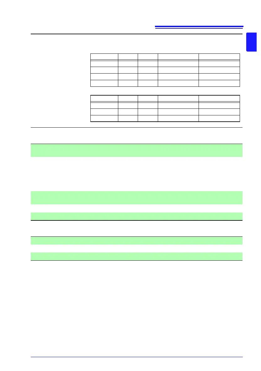
Default setting Measurement method: 4-wire, Scan function: Auto, FAIL stop: OFF, channel
default settings as follows (default measurement conditions)
4-wire
2-wire
Channel no. Channel Unit A terminal B terminal
1 Enabled 1 TERM1 TERM2
2 to 10 Disabled 1 TERM2 to TERM10 TERM3 to TERM11
11 to 20 Disabled 2 TERM1 to TERM10 TERM2 to TERM11
21 to 42 Disabled 1 TERM1 TERM2
Channel no. Channel Unit A terminal B terminal
1 Enabled 1 TERM1 TERM2
2 to 21 Disabled 1 TERM2 to TERM21 TERM3 to TERM22
22 to 42 Disabled 2 TERM1 to TERM21 TERM2 to TERM22
Output Resistance measured value (display value after zero-adjustment and temper-
ature correction but before scaling and ΔT calculation)
Output voltage 0 V (corresponds to 0 dgt.) to 1.5 V DC*
If a measured value fault occurs, 1.5 V; if the measured value is negative, 0 V
* For a 1,200,000 dgt. display, corresponds to 1.2 V (1,200,000 dgt.).
For a 120,000 dgt. display, corresponds to 1.2 V (120,000 dgt.).
For a 12,000 dgt. display, corresponds to 1.2 V (12,000 dgt.).
For a display in excess of 1.5 V, fixed at 1.5 V.
Maximum output
voltage
5 V
Output impedance 1 k
Number of bits 12bit
Output Comparator judgment output (two outputs: Hi and Lo/IN)
Output jack 3-pole earphone jack (φ2.5 mm)
Output voltage 5 V±0.2 V DC, 20 mA