Appendix 7 Unstable Measured Values
A13
Appendix
(3) Multi-Point Contacts with Clip Leads
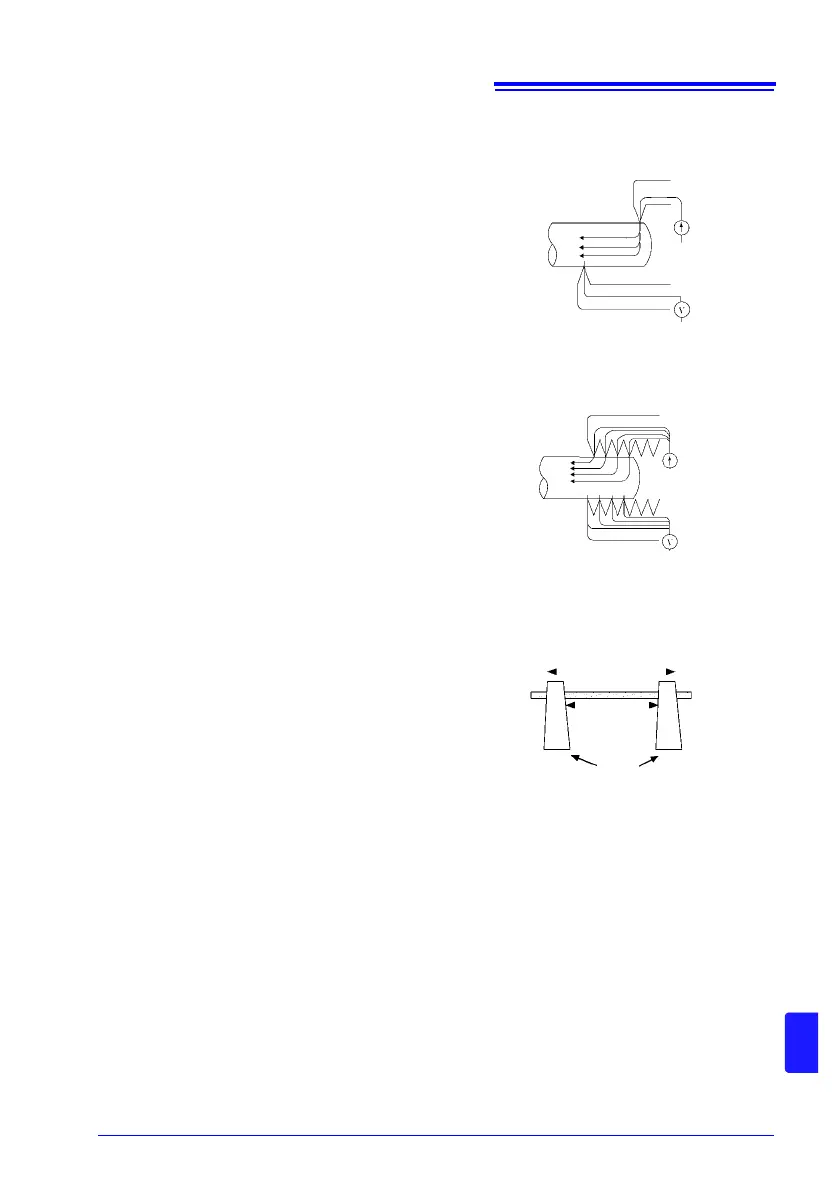
The ideal conditions for four-terminal measurements
are shown in Fig. 3: current flows from the far probe
and voltage is detected with uniform current distribu-
tion.
To facilitate measurement, the tips of the Model
L2101 Clip Type Lead are jagged.
When a clip is opened as shown in Fig. 4, measure-
ment current flows from multiple points, and voltage
is detected at multiple points. In such cases, the
measured value varies according to the total contact
area.
Additionally, as shown in Fig. 5, when measuring the
resistance of a 100 mm length of wire, the length
between the nearest edges of the clips is 100 mm,
but the length between the farthest edges of the
clips is 110 mm, so the actual measurement length
(and value) has an uncertainty of 10 mm (10%).
If measured values are unstable for any of these
reasons, maximize stability by measuring with point
contacts as far as possible.
Figure 3. Ideal Four-Terminal Method
SENSE B, (SENSE A)
(Voltage Detection)
SOURCE B, (SOURCE A)
(Current Source)
Figure 4. Measurement with
Model L2101 Clip Type Lead
SENSE B, (SENSE A)
(Voltage Detection)
SOURCE B, (SOURCE A)
(Current Source)
Figure 5. Measuring the resistance of
a 100 mm length of wire
Clips
110 mm
100 mm