Appendix 7 Unstable Measured Values
A15
Appendix
(6) Measurement target Becomes Warm
The maximum applied power to a measurement target by this instrument is determined as
follows. The resistance of samples with small thermal capacity can change due to heating.
In such cases, enable low-power measurement.
(7) Effects of thermal EMF
When there is a junction between different metals and a temperature difference between
the junction and the area being observed, thermal EMF occurs. In light of use of copper
measurement leads, nickel-plated connectors, and solder containing tin, it is not practical to
ensure that only the same metals are used in connections. For more information about how
to deal with errors caused by thermal EMF, see "Appendix 9 Effect of Thermal EMF"
(p.A23).
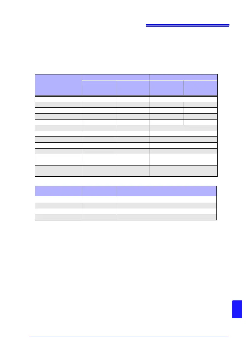
• Low-power: OFF
Range
High Low
Measurement
current
Maximum power
in measurement
range
Measurement
current
Maximum power
in measurement
range
10 m 1 A 12 mW −
100 m 1 A 120 mW 100 mA 1.2 mW
1000 m 100 mA 12 mW 10 mA 120 W
10 10 mA 1.2 mW 1 mA 12 W
100 10 mA 12 mW 1 mA 120 W
1000 1 mA 1.2 mW −
10 k 1 mA 12 mW −
100 k 100 A 1.2 mW −
1000 k 10 A 120 W −
10 M 1 A 12 W −
100 M
(
precision mode: ON)
100 nA 1.2 W −
100 M, 1000 M
(
precision mode: OFF)
1 A or less 1.3 W −
• Low-power: ON
Range
Measurement
current
Maximum Applied Power
= (Measured Resistance) × (Measurement Current)
2
1000 m 10 mA 120 W
10 1 mA 12 W
100 1 mA 120 W
1000 100 A 12 W