Appendix 19 Calibration
A41
Appendix
• For more information about 0 calibration connections, see "Appendix 6
Zero Adjustment" (p.A7).
• Adequate noise countermeasures must be implemented during high-resis-
tance and low-resistance measurement, when using the low measurement
current setting, and during low-power resistance measurement.
In a highly noisy environment, the measured value may become unstable or
inaccurate. In addition, the measurement error detection function may react
and no measured value may be displayed. Connect the metal exterior of
standard resistors and dial resistors to the instrument’s GUARD potential.
See: "Appendix 7 Unstable Measured Values" (p.A12)
• Do not use alligator clips with the voltage detection terminals. Thermal
EMFs may cause measured values to diverge.
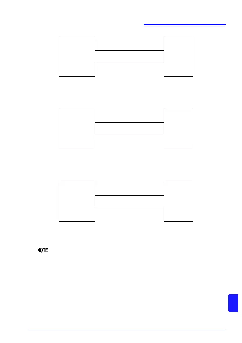
TEMP.SENSOR
FLUKE
5520A
Hi
Lo
HIOKI
RM3545
Wire resistance: 500 m or less
(circuit resistance)
(No polarity)
Temperature measurement (Thermistor)
TEMP.
ANALOG
INPUT
HIOKI
SS7012
+
−
HIOKI
RM3545
Wire resistance: 100 or less
(circuit resistance)
Temperature (Analog input)
+
−
D/A OUTPUT
HIOKI
3237
V
HIOKI
RM3545
Wire resistance: 100 or less
(circuit resistance)
D/A output
+
GND COM