4.3 Zero Adjustment
69
4
• If a resistance that is smaller than the resistance value when zero-adjustment was per-
formed is measured, the measured value will be negative.
Example: If you set an offset of 50 m for the 100 m range
If you measure 30 m, -20 m will be displayed.
• When using the multiplexer, zero-adjustment can be performed by scanning all channels.
See: "8.5 Zero Adjustment (When a Multiplexer Unit Has Been Installed)" (p.163)
Allow the instrument to warm up for 60 minutes before performing zero-adjustment.
Performing zero-adjustment
1
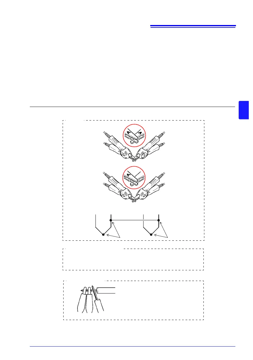
Short the measurement leads together.
Red
SOURCE
SOURCE
SOURCE
SENSE
SENSE
SENSE
Red
Black
Black
SOURCE
SENSE
Bring the "V" marks together
at the same position.
Connection
Connection
SENSE A SENSE B
SOURCE A SOURCE B
L2104 (option)
L2101
L2102, L2103 (options)
Since zero-adjustment cannot be performed with the L2102 or L2103,
use the L2101 Clip Type Lead or other lead type to perform zero-ad-
justment.
Place the alligator clips on the outside
and the lead rods on the inside when
performing zero-adjustment.
Correct
Incorrect