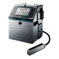
3-49
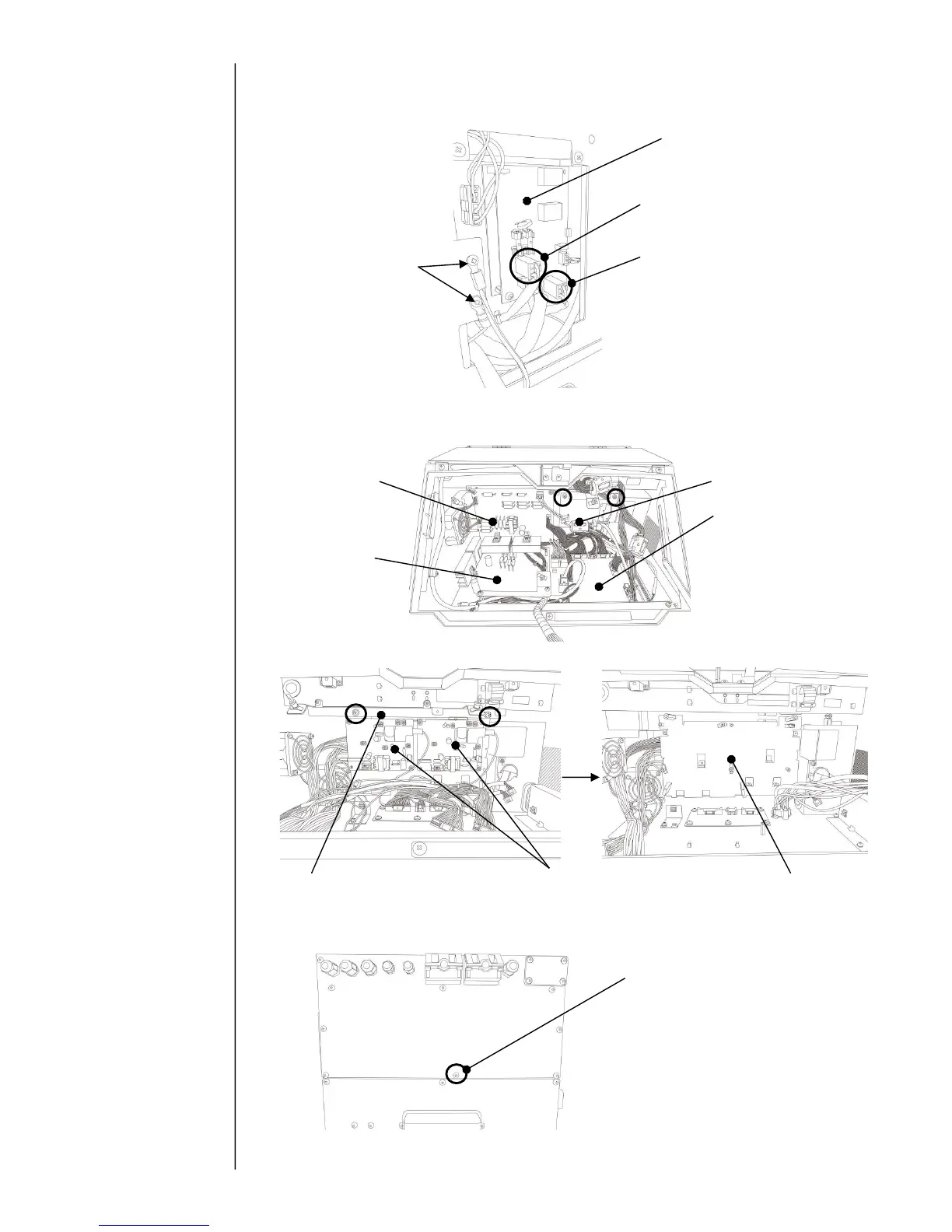
(3) Remove the side cover, and then disconnect the connectors of CN1 and CN3 for multiple
power supply.
(4) Open maintenance door. Remove the parts of ① to ⑥ in order.
(5) Remove the fixing screw of back cover.
In order to access the
high voltage power
supply, refer to “3.3.16
high voltage power
supply ”.
Ground wire
(yellow and green)
CN3: Connector for Multiple power supply 1
Fixing screw for Multiple power supply 2
(1 piece) .
⑥ High voltage power
supply 1 and 2
⑤ Metal plate for spacer fixing protective
cover.(Remove the fixing screws(2pcs) circled.)
Multiple power supply 1
(High voltage power supply 1 and
2 are removed)
③ Fixing metal for charge
harness (Remove two(2) fixing)
CN1: Connector for Multiple power supply 2
 Loading...


