5-23
5.12 Head base Replacement Procedure
When the head base is damaged, it must be replaced. Follow the procedures below for replacement.
1 Remove the head cover and heater cover.
2 Remove the nozzles described in the item 5.8.
3 Remove the deflection base described in the item 5.11.
4 Remove the shutoff valves (MV9/MV29) described in the item 5.5.
5 Remove the heating unit described in the item 5.6.
6 Remove the gutter base described in the item 5.3.
7 Remove the FG.
8 Remove the fixing screws of the APH sensor board.
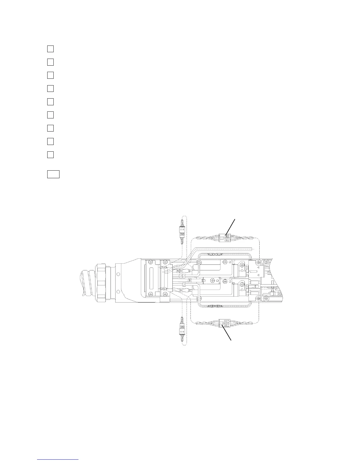
9 Unscrew the fastening screws between the head base and the head cable,
and remove the head base.
10 Attach the new head base.
[Caution]
Do not mix up lead wires and tubes which are placed either at the front face (nozzle side)
or placed at the back face (high voltage cable side).
Front face: Ink-furnishing tube (E), cleaning tube (R, RR), circulation tube (J, JJ), air purge
 Loading...


