3-50
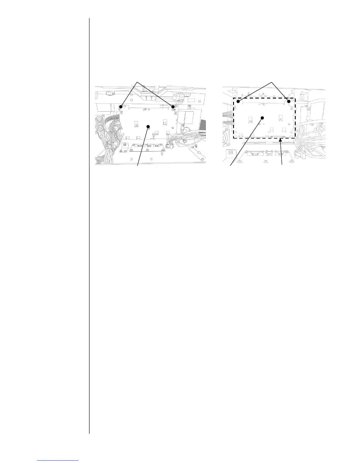
(6) Remove hexagonal metal spacer (2pcs) for Multiple power supply 1 and remove Multiple
power supply1.
(7) Remove fixing screws (2pcs) for Multiple power supply 2 and remove Multiple power
supply 2. ※ Since Multiple power supply 2 is sticked n near cover by double – sided
tape, peel it off strongly when you remove it.
(8) Replace Multiple power supply and reassemble the removed parts in reverse order.
Check the clamp position of harness and connectors on EZJ133, 134, 139 and 125
board.
(9) Check if IJP is started up properly by turning power ON. If CN2 and CN28 onEZJ133
board are connected wrongly, the screen display can not be lit up. In this case, check if
those connected properly or not.
(10) Check if print operation can be made by respective nozzles by turning the main power
switch ON.
With respect to the
clamping position of wire
harness, refer to “3.3.20
Electrical connection
diagram”.
 Loading...


