2-7
Main causes of automatic adjustment failure
The connection of the EZJ133 board and EZJ125 board is insufficient.
(Nozzle 1)
The connection of the EZJ133 board and EZJ134 board is insufficient.
(Nozzle 2)
The dip switch on the EZJ125 board is incorrectly set.(Nozzle 1)
The dip switch on the EZJ134 board is incorrectly set.(Nozzle 2)
The connection of the coaxial cable connector for excitation (EZJ125 CN5:
Nozzle 1, EZJ134 CN7:Nozzle2) is insufficient.
Replacement parts are out of order (EZJ133/EZJ125/EZJ134 board, nozzle,
head cable).
EZJ125 board work “A” and EZJ 125 work “B” is faultily installed the wrong way
around.
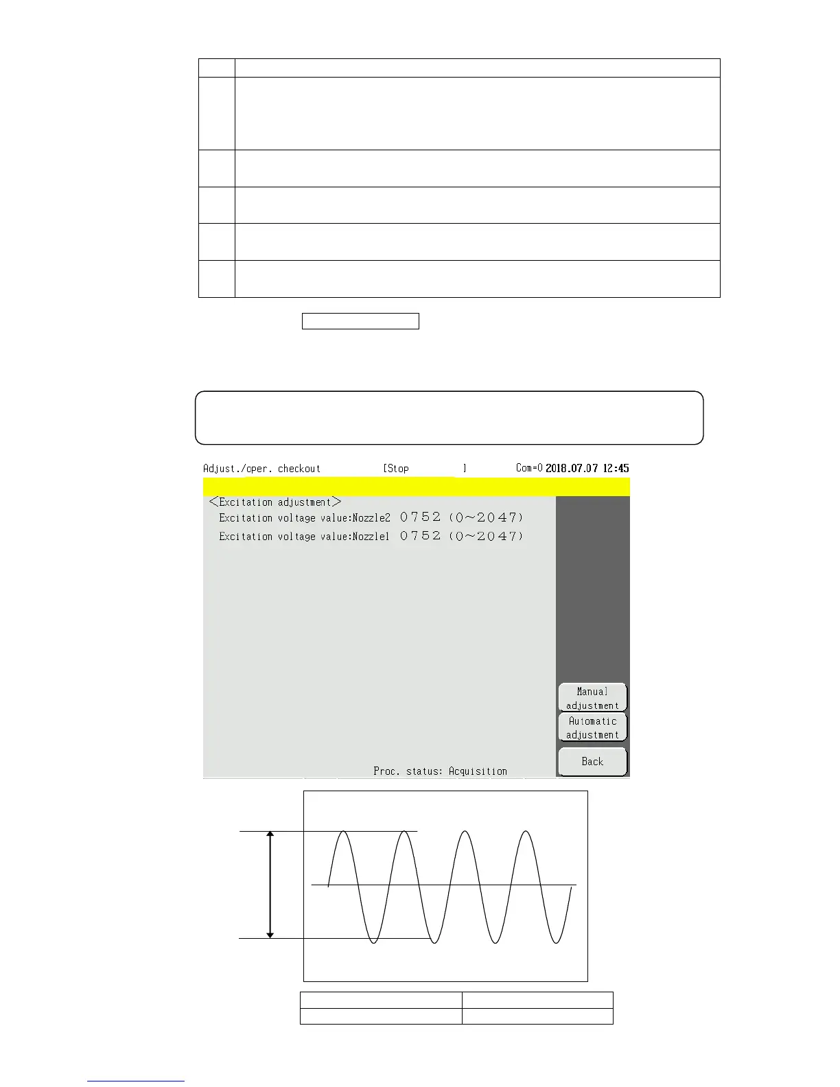
When you press Manual adjustment and manually input the excitation voltage adjustment
value, the excitation voltage value is increased or decreased. Check the waveform of TP14
(excitation voltage:Nozzle 1) on the EZJ125 board and TP3(excitation voltage:Nozzle 2) on
the EZJ134 board with an oscilloscope.
[Waveform of excitation voltage]
For the position of the board and test pins, refer to “3.3.5 EZJ125 board” and
“3.3.6 EZJ134 board”.
 Loading...


