E1 Series Servo Drive User Manual Application Function
HIWIN MIKROSYSTEM CORP. 8-5
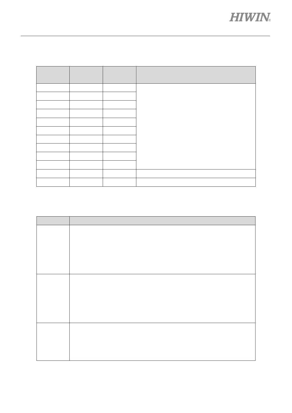
Parameter setting values and hardware pin assignment
Table8.1.1.3
Setting
Signal CN6 Pin Description
0 I1 33
Hardware pin can be set to activate or deactivate the
allocated digital input function when signal is input or
is not input. Refer to table 8.1.1.2.
Pt511, Pt512 and Pt513 are used to set the pin
polarity of I1~I10 signals. Refer to table 8.1.1.4.
1 I2 30
2 I3 29
3 I4 27
4 I5 28
5 I6 26
6 I7 32
7 I8 31
8 I9 9
9 I10 8
A - - The signal is always active.
B - - The signal is always inactive.
Set pin polarity
Table8.1.1.4
Parameter Description
Pt511
Pt511 t.XXXX is used to set the pin polarity of I1~I4 signals. Setting value 0 means
the digital input function is activated as signal is input and is deactivated as signal is
not input. Setting value 1 means digital input function is activated as signal is not
input and is deactivated as signal is input.
t.X Set the pin polarity of I1 signal.
t.X Set the pin polarity of I2 signal.
t.X Set the pin polarity of I3 signal.
Set the pin polarity of I4 signal.
Pt512
Pt512 t.XXXX is used to set the pin polarity of I5~I8 signals. Setting value 0 means
the digital input function is activated as signal is input and is deactivated as signal is
not input. Setting value 1 means the digital input function is activated as signal is
not input and is deactivated as signal is input.
t.X Set the pin polarity of I5 signal.
t.X Set the pin polarity of I6 signal.
t.X Set the pin polarity of I7 signal.
Set the pin polarity of I8 signal.
Pt513
XX is used to set the pin polarity of I9~I10 signals. Setting value 0
means the digital input function is activated as signal is input and is deactivated as
signal is not input. Setting value 1 means the digital input function is activated as
signal is not input and is deactivated as signal is input.
t.X Set the pin polarity of I9 signal.
t.X Set the pin polarity of I10 signal.

 Loading...


