E1 Series Servo Drive User Manual Parameters
15-40 HIWIN MIKROSYSTEM CORP.
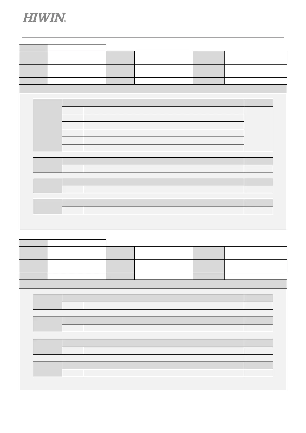
Size 2
0000~5555 Default 2114
Name
Output signal
selection 1
Unit -
All
Description
t.X
Allocation of alarm output (ALM) signal Reference
0 Disabled
-
1 Output signal from CN6-35 and 34 (O1).
2 Output signal from CN6-37 and 36 (O2).
3 Output signal from CN6-39 and 38 (O3).
4 Output signal from CN6-11 and 10 (O4).
Output signal from CN6-40 and 12 (O5).
t.X
Allocation of positioning completion output (COIN) signal Reference
0~5 The allocation is the same as the one of alarm output (ALM) signal. -
t.X
Allocation of velocity reach output (V-CMP) signal Reference
0~5 The allocation is the same as the one of alarm output (ALM) signal. -
t.X
Allocation of rotation detection/movement detection output (TGON) signal
0~5 The allocation is the same as the one of alarm output (ALM) signal. -
Size 2
0000~5555 Default 0003
Name
Output signal
selection 2
Unit -
All
Description
t.X
Allocation of drive ready output (D-RDY) signal Reference
0~5 The allocation is the same as the one of alarm output (ALM) signal. -
t.X
Allocation of servo ready output (S-RDY) signal Reference
The allocation is the same as the one of alarm output (ALM) signal.
t.X
Allocation of torque limit detection output (CLT) signal
0~5 The allocation is the same as the one of alarm output (ALM) signal. -
t.X
Allocation of velocity limit detection output (VLT) signal Reference
0~5 The allocation is the same as the one of alarm output (ALM) signal. -

 Loading...


