E1 Series Servo Drive User Manual Parameters
HIWIN MIKROSYSTEM CORP. 15-41
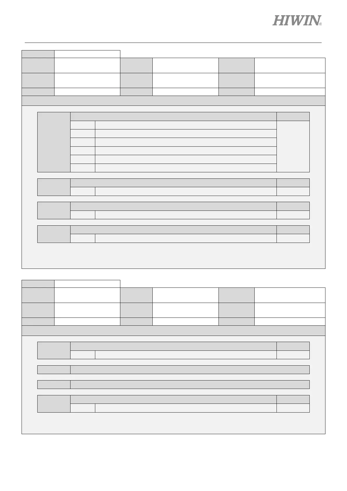
Size 2
0000~5555 Default 0005
Name
Output signal
selection 3
Unit -
All
Description
t.X
Allocation of brake control output (BK) signal Reference
0 Disabled
-
1 Output signal from CN6-35 and 34 (O1).
2 Output signal from CN6-37 and 36 (O2).
3 Output signal from CN6-39 and 38 (O3).
4 Output signal from CN6-11 and 10 (O4).
Output signal from CN6-40 and 12 (O5).
t.X
Allocation of warning output (WARN) signal Reference
0~5 The allocation is the same as the one of brake control output (BK) signal. -
t.X
Allocation of positioning near output (NEAR) signal Reference
0~5 The allocation is the same as the one of brake control output (BK) signal. -
t.X
Allocation of command pulse multiplication switching output (PSELA) signal
0~5 The allocation is the same as the one of brake control output (BK) signal. -
Size 2
0000~5005 Default 0000
Name
Output signal
selection 4
Unit -
All
Description
t.X
Allocation of position trigger digital output (PT) signal Reference
0~5 The allocation is the same as the one of brake control output (BK) signal. -
t.X Reserved (Do not modify.)
t.X Reserved (Do not modify.)
t.X
Allocation of servo drive homing completion output (HOMED) signal Reference
0~5 The allocation is the same as the one of brake control output (BK) signal. -

 Loading...


