IFP-75/IFP-75HV Installation/Operation Manual — P/N LS10147-001SK-E:D 06/25/2021 37
RA-1000 Remote Annunciator Installation Control Panel Installation
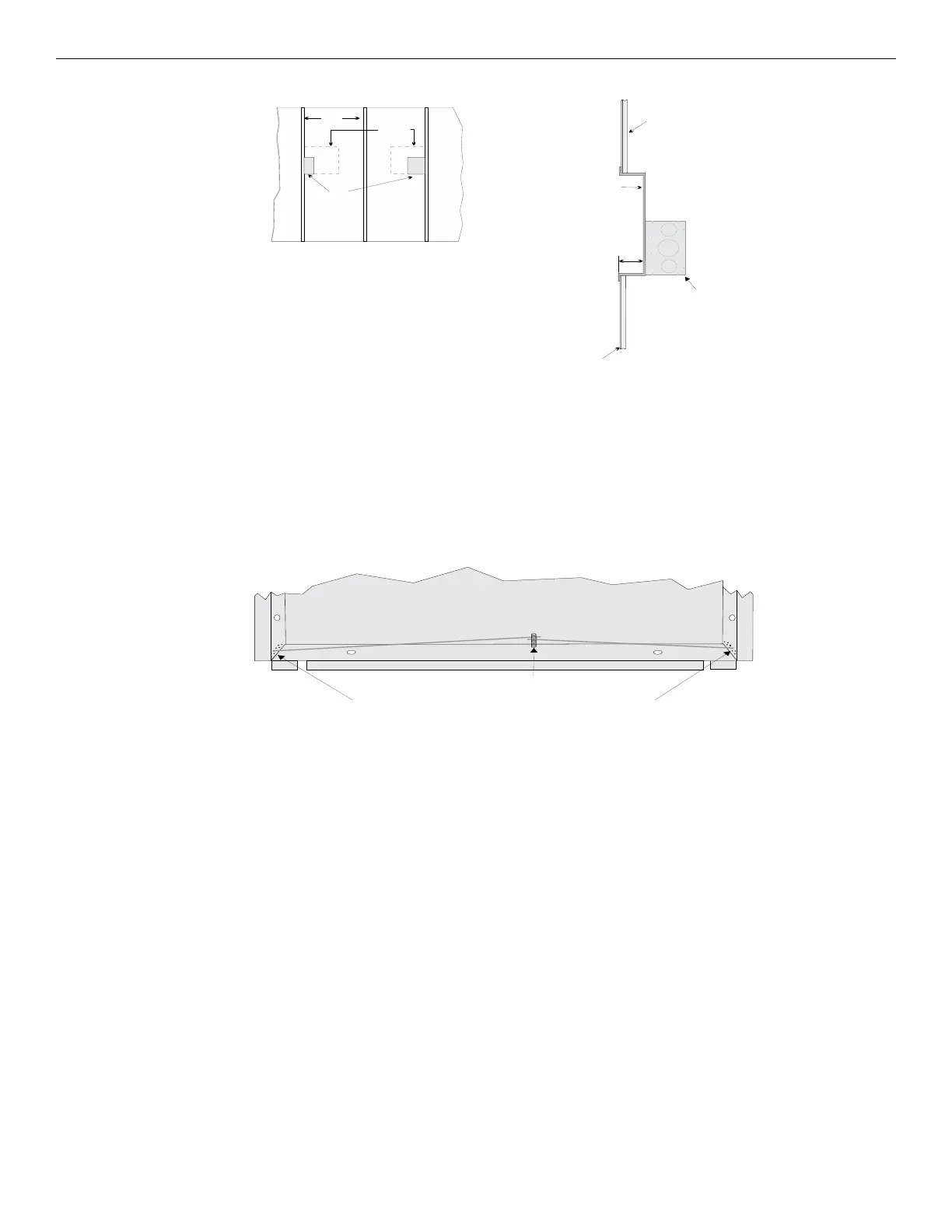
Figure 4.23 Placement of Electrical Box for Flush Mounting
Flush Mounting Steps
1. Cut a hole in the sheet rock to the following dimensions: 8-1/4” W x 6-5/8”H. If an electrical box is used, the box must be 1-3/8” back
from face of wall to accommodate the annunciator (see Figure 4.23).
2. Remove knockout holes as needed for wires.
3. Fit the annunciator back box into the hole and stabilize with mounting wires. Angle the mounting wires into the first hole past the sheet
rock. Secure the wires behind the screws as shown in Figure 4.24. When all four wires are in place, the back box should fit snugly into
the hole in the sheet rock.
4. After the annunciator wiring to the panel has been completed (described in Section 4), replace the electronic assembly in the back box.
Place the bezel over the back box and tighten the set screws on the bezel.
.
Figure 4.24 Flush Mounting the Back Box
Sheet rock
Sheet rock
Electrical Box
Annunciator
back box
1-3/8"
When flush-mounting using an
electrical box, the box must be
1-3/8" from face of wall.
Electrical box applications require
2 by 4 construction minimum.
studs
electrical
box
annunciator
back box
(outline)
wall
Examples of Electrical Box Use
Electrical Box Placement
Insert wires at an angle into the first holes past the sheet rock.
Secure the wires behind this screw.
Attach second set of wires to top of back box.

 Loading...


