IFP-75/IFP-75HV Installation/Operation Manual — P/N LS10147-001SK-E:D 06/25/2021 57
SK-NIC Wiring Options Networking Common Communicator List
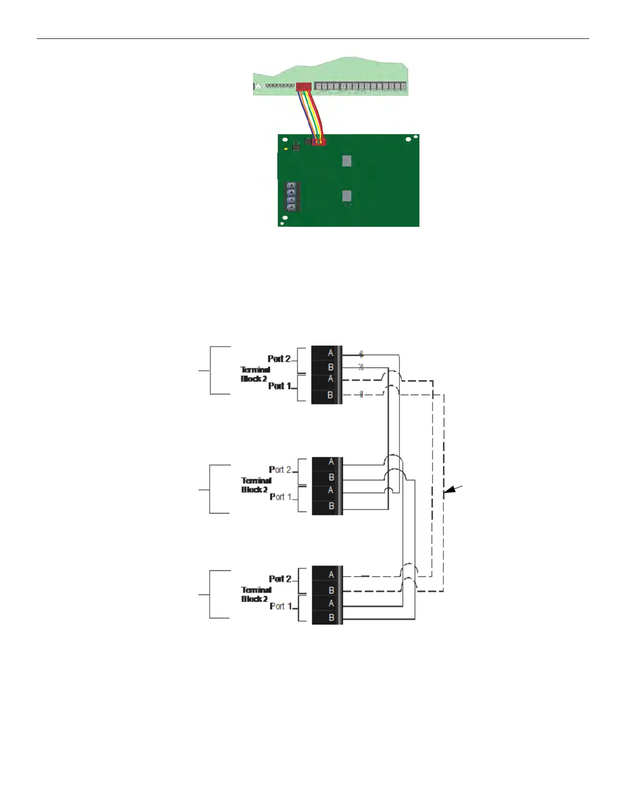
Figure 5.5 Panel to SK-NIC connection
3. Each SK-NIC has the ability to monitor for earth ground faults on the twisted pairs connected to Port 1 of its terminal block TB2. Earth
fault detection for any wiring at Port 2 of TB2 is done at the next/previous SK-NIC due to these wiring connections being connected to
Port 1 of TB2 at the next/previous SK-NIC.
4. Unused optic ports on fiber loop modules must have their dust caps placed on the port.
5. Based on the type of data medium chosen, run the twisted pair wiring/fiber optic cable to the next SK-NIC using a Class B or
Class X wiring method. A combination of both medium types can be used. See Figure 5.6, Figure 5.7, Figure 5.8, and Figure 5.9 for the
SK-NIC wiring examples.
Unshielded Twisted-Pair Wiring between Multiple Panels
Unshielded twisted-pair wiring between multiple panels is shown in Figure 5.6. Class X wiring is shown with a dotted line.
Figure 5.6 Twisted-Pair Wiring Configuration
Fiber-Optic Multi-Mode Wiring between Multiple Panels
Fiber-optic cable between multiple panels is shown in Figure 5.7. Class X is shown with a dotted line.
LAST
CONTROL
PANEL
SK-NIC
NEXT
CONTROL
PANEL
SK-NIC
FIRST
CONTROL
PANEL
SK-NIC
Class X
Wiring

 Loading...


