Thor VM3 with Microsoft Windows Embedded Compact 7 User Guide 91
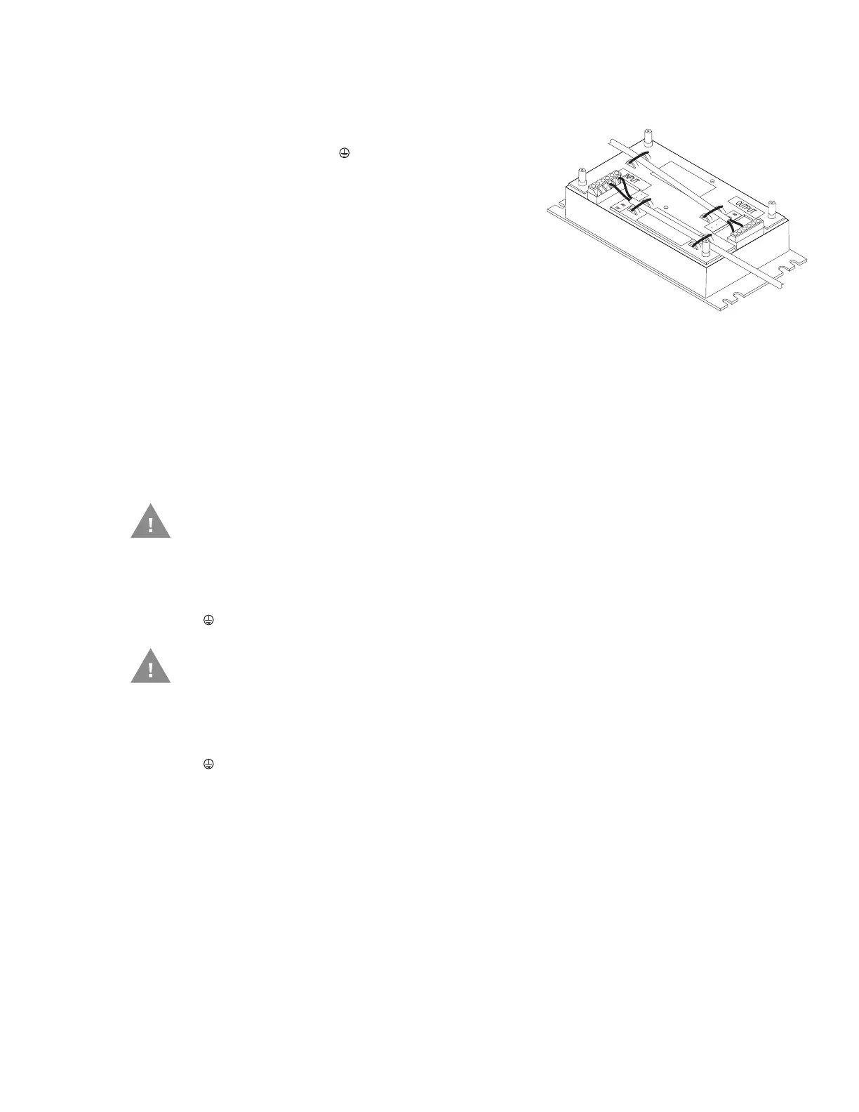
7. Connect the stripped end of the negative wires (black and black/white twisted
together) to the output. See Power Cable Identification.
Note: The input and output blocks each have two + (plus),
two – (minus) and two (ground) connectors.
Either connector in the block can be used to
connect the matching polarity wire.
8. Route the wiring from the DC/DC power supply to the vehicle’s electrical system. Do
not connect to vehicle power at this time.
9. Strip the wire ends and connect to the input side of the DC/DC power supply.
10. Use looms and wire ties to secure all wiring as shown.
11. Reattach the cover with the screws.
12. Connect the DC/DC power supply to the vehicle’s electrical system as directed
below
• + is connected to battery positive.
• - must be connected to battery negative.
• must be connected to the vehicle chassis ground.
• + is connected to battery positive.
• - is connected to battery negative.
• is connected to the vehicle chassis ground, which can also be battery negative.
13. While observing the Fuse Requirements, connect the power cable as close as
possible to the actual battery terminals of the vehicle. When available, always
connect to unswitched terminals in the vehicle fuse panel, after providing proper
fusing.
ATTENTION: For uninterrupted power, electrical supply connections should not be
made at any point after the ignition switch of the vehicle.
14. Use proper electrical and mechanical fastening means for terminating the cable.
Properly sized “crimp” type electrical terminals are an accepted method of
termination. Select electrical connectors sized for use with 18AWG (1mm
2
)
conductors.
Caution: For battery powered vehicles:
Caution: For internal combustion engine powered vehicles:

 Loading...