Function Blocks
Function Block Reference Guide 3/9912
2.4 4ADD Function Block,
continued
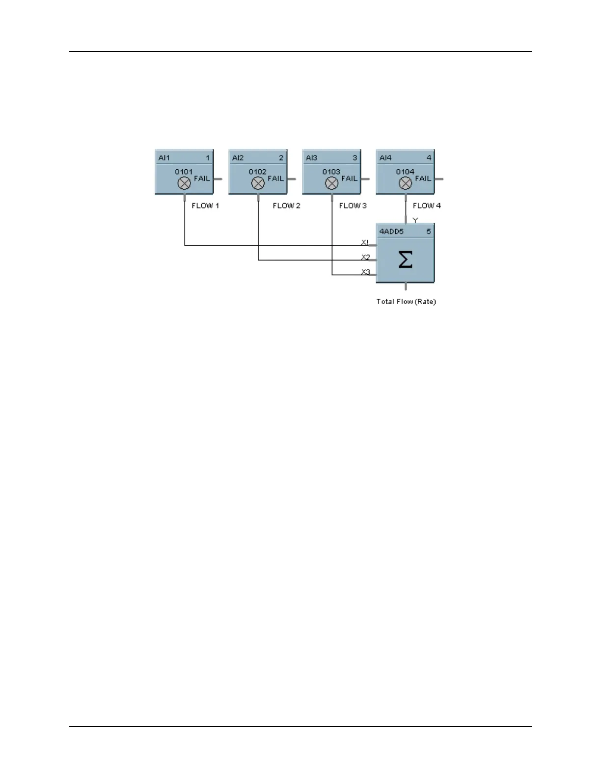
4ADD Example
Figure 2-3 shows a Function Block diagram using a 4ADD function block to find the total Flow rate as the
sum of Flow 1, Flow, 2, Flow 3, and Flow 4.
Figure 2-3 4ADD Function Block Example