Function Blocks
3/99 Function Block Reference Guide 161
2.51 PT Function Block,
continued
Configuration Parameters,
continued
Table 2-45 PT Function Block Configuration Parameters,
continued
Properties Group Parameter Index# Parameter Description Value or Selection
Start Hour
N/A Start Hour 0 through 23
Minute
N/A Start Minute 0 through 59
Second
N/A Start Second 0 through 59
Day
N/A Start Day
Monthly
- 1 - 31
(Days >31 = 31)
If the current month’s
last day is less than 31
it will turn ON on the
last day of the month.
Weekly
-Monday
through Sunday
Cycle Hour
N/A Cycle Hour 0 through 23
Minute
N/A Cycle Minutes 0 through 59
Second
N/A Cycle Seconds 0 through 59
Example
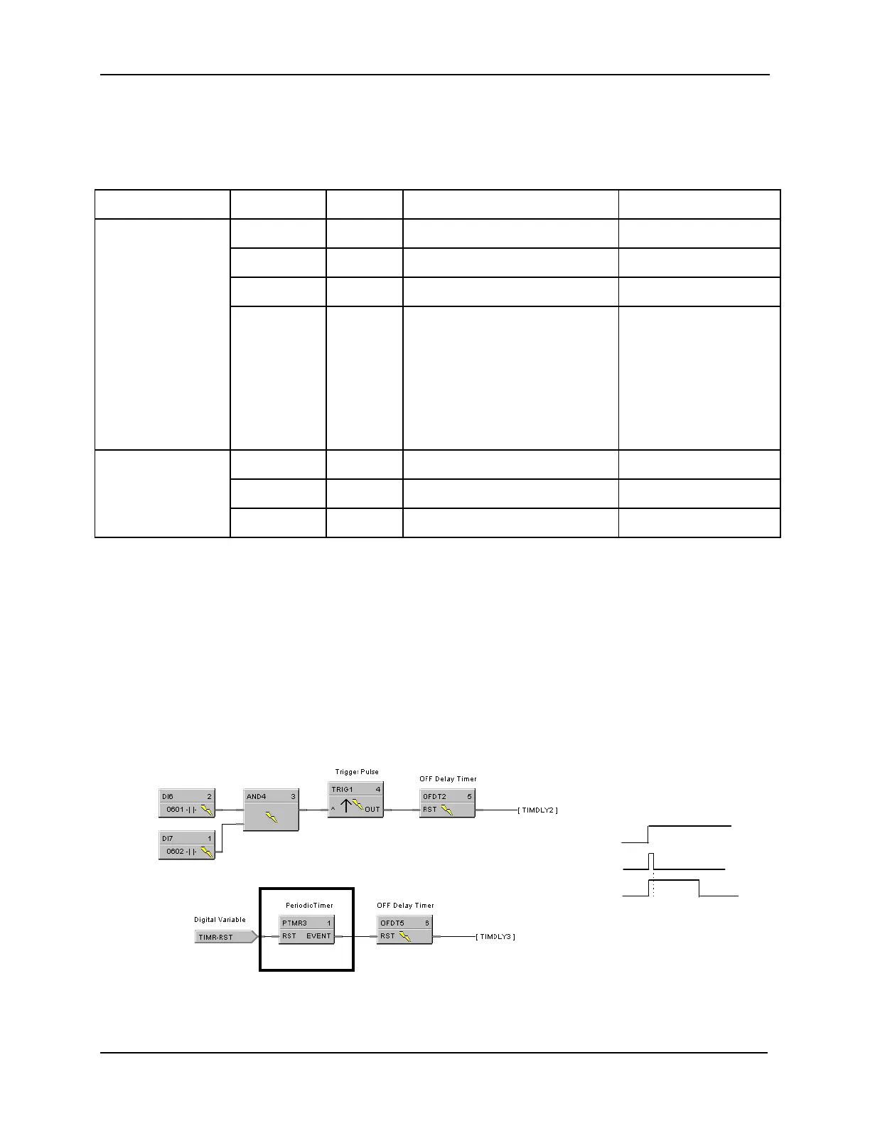
Figure 2-53 shows a Function Block Diagram using a PT function block
An OFF delay timer block output is ON as long as the RST input is logic HI (ON). It can be used for time
duration but must be triggered by an ON to OFF transition on the Reset input. This can be accomplished
using Trigger blocks (TRIG) to create one-shot pulses which last one scan cycle. The fast logic trigger
pulse will last 100 ms. while the normal logic trigger pulse will last the complete scan cycle for analog
blocks. Use according to application need. A
Periodic Timer (PT)
output pulse may also be used to start
the timer for the OFF delay for time duration.
Off delay
AND4 output
TRIG1 output
OFDT2 output
Timing Diagram
Figure 2-53 PT Function Block Example
 Loading...


