Function Blocks
3/99 Function Block Reference Guide 107
2.38 MSF Function Block,
continued
Input
X = Differential pressure analog value.
Y = Gas pressure analog value.
Z = Gas Temperature analog value.
Output
OUT = Calculated analog value
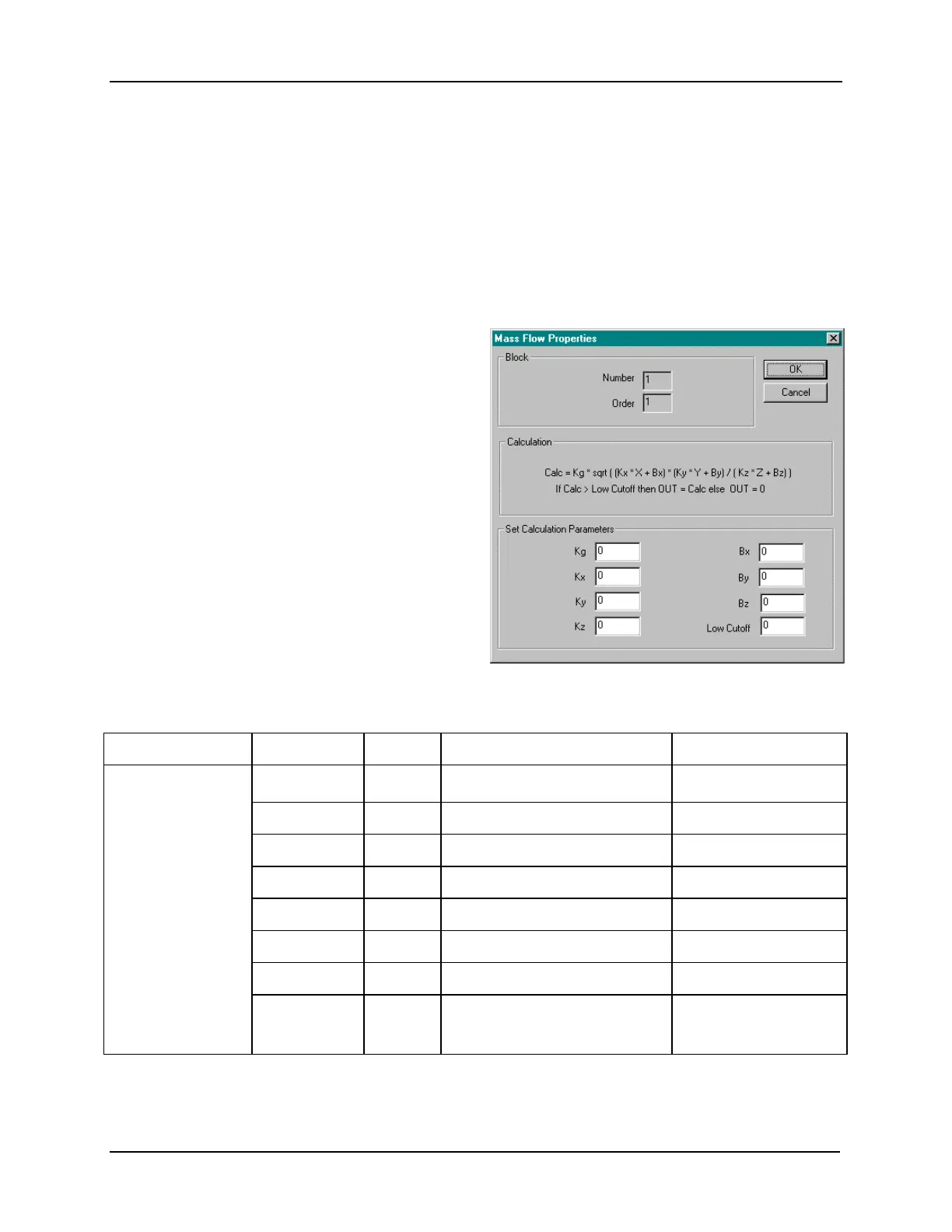
Block Properties
Double click on the function block to access the
function block properties dialog box.
Block Order (Read Only)
You can change the assigned execution order
number by selecting “Execution Order” in the
“Configure” menu and arrange the order to suit
your control strategy.
Configuration Parameters
You must configure the MSF function Block
parameters to the desired value or selection that
matches your operating requirements.
Table 2-31
describes the parameters and the
value or selection.
Table 2-31 Mass Flow Function Block Configuration Parameters
Properties Group Parameter Index# Parameter Description Value or Selection
Set Calculation
Parameters
K
q
0
Orifice constant –99999 to 999999
K
x
1
Delta pressure scaler –99999 to 999999
K
y
2
Pressure scaler –99999 to 999999
K
z
3
Temperature scaler –99999 to 999999
B
y
4
Pressure bias –99999 to 999999(EU)
B
x
5
Delta pressure bias –99999 to 999999(EU)
B
z
6
Temperature bias –99999 to 999999(EU)
Low Cutoff
7
Low Dropoff Value sets the output
to zero when the calculation is
below this limit.
0 to 99999 in
Engineering Units
Continued next page
 Loading...


