Function Blocks
3/99 Function Block Reference Guide 13
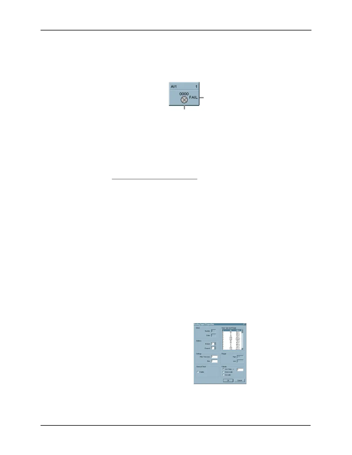
2.5 AI Function Block
Description
The
AI
label stands for
Analog Input
. This block is part of the
Loops
category. It looks like this
graphically on the Control Builder.
Function
Read value of an Analog Input from a specified real I/O address. Convert analog input value to
corresponding output (OUT) in engineering units based on the necessary scaling and conversions
performed.
LINEAR - converts analog input value to corresponding output in units based on a linear 0 to 100% scale
and specified high and low range values.
OUT = Scale x Input value + Bias
where:
Scale = High Range Value - Low range value
100
Input value = Analog Value in percent
T/C or RTD - converts analog input value in engineering units using the range of Input Type.
Note: The failsafe detection on this input block configured for 4-20mA range is:
Low Detection: -3.2mA
High Detection: 21.6mA
Outside of the range the flag (Input Fail) is ON. There is no detection from 0 to 4 mA, but the
block continues to work and provide data which could be compared via an Alarm Block.
Input
•
Analog value from specified real I/O address.
Output
OUT = Analog Input value in engineering units.
FAIL = Digital status of channel
Digital Low (0) = OK
Digital High (1) = Open sensor or failed input channel.
Configuration Parameters
This is a view of the AI Properties Dialog
box.
You must configure the AI function block
parameters to the desired values or
selections that match your operating
requirements.
Table 2-2 describes the parameters and the
value or selection.
Out
 Loading...


