Function Blocks
3/99 Function Block Reference Guide 115
2.43 ONDT Function Block,
continued
Table 2-32 On Delay Timer Function Block Example
Properties Group Parameter Index# Parameter Description Value or Selection
Time Delay Time delay
0 Delay Time - specifies the
amount of time the ON state
logic output will occur after an
OFF to ON transition of the
RUN input.
0.1 sec, 0 to 9999.9
Enter as 0.1 to 99999 in
0.1 increments
Example
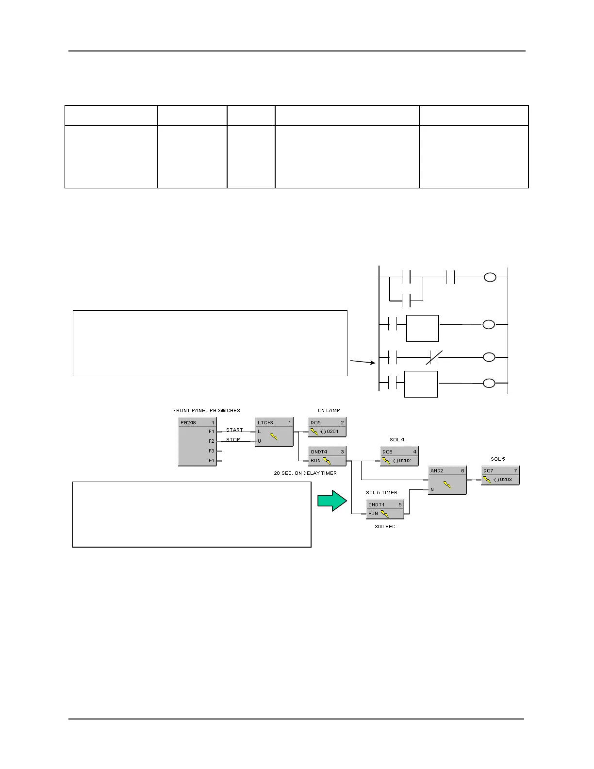
Figure 2-40 shows a Function Block Diagram using an ONDT function block.
Start Stop
DO 1
DO 1
DO 1
ON Timer
1
20 SEC
DO 2
On Lamp
SOL 4
SOL 5
DO 3
ON Timer
2
300 SEC
DO 2
CR1
CR1
DO 2
The application requirement is to turn on a pump, a compressor, etc. for
a fixed period of time - a common use for timers. This application, the
turn on of Pump2 for 300 sec., requires two additional rungs of ladder
logic. After SOL4 is turned ON, SOL 5 (Pump 2) is also turned ON
since CR1 (NC) is OFF (logic true). When ON Delay Timer 2 times out
after 300 sec., the CR1 coil is turned ON which turns off SOL 5.
PLC Ladder Logic
UMC 800 Logic
In UMC logic, the output of ONDT4 timer activates the
ONDT1 timer directly and is also an input for a 2-IN AND
gate, whose output activates the DO for SOL5. After ONDT1
times for 300 sec., its output turns ON, disabling the AND
gate output which de-energizes the DO. Three (3) additional
function blocks are used.
Figure 2-40 ONDT Function Block Example
 Loading...


