Function Blocks
Function Block Reference Guide 3/9970
2.21 DO Function Block,
continued
Table 2-21 Digital Output Configuration Parameters
Properties Group Parameter Index# Parameter Description Value or Selection
Address I/O Module
N/A Address of select I/O Module
From 1 to 16
Channel
Channel on selected I/O Module
From 1 to 6
1
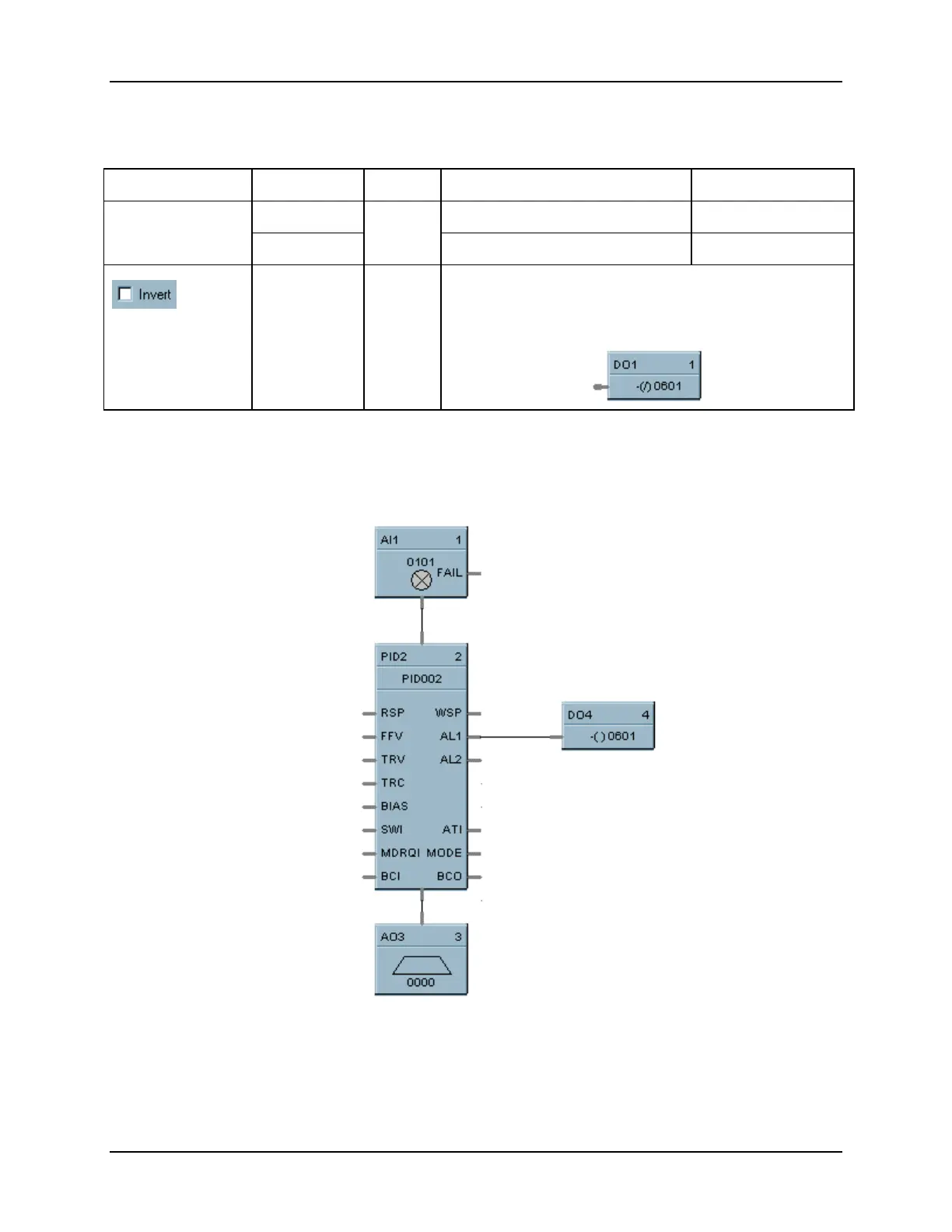
If INVERT is selected, Invert IN before writing to output
The slash will be present in the COIL symbol only when
the invert box is selected on the dialog box. (see below)
Example
Figure 2-19 shows a Function Block Diagram using a DO function block. A digital output signal from PID
block AL1 will turn the Digital Output block ON & OFF for remote alarming. This output could be OR’d
with other alarm outputs if going to a common alarm relay.
Figure 2-19
DO Function Block Example
 Loading...


