Function Blocks
Function Block Reference Guide 3/9936
2.11 AO Function Block,
continued
Configuration Parameters,
continued
Table 2-8 Analog Output Configuration Parameters
Properties Group Parameter Index# Parameter Description Value or Selection
Block Order
N/A Execution Order for Block
Read Only. See “Configure’
Menu, ”Execution Order” to
change.
Address I/O Module
Address of selected I/O
module (must match model
selection guide)
Enter a value:
from 4 to 10
Channel
Channel on selected I/O
Module
Enter a value:
from 1 to 4
Range Range Hi
1 High Range Value
Engineering Unit - value of
input that corresponds to
100% output value
-99999 to 999999
Default = 100
Range Low
2 Low Range Value
Engineering Unit - value of
input that corresponds to 0%
output value
-99999 to 999999
Default = 0.0
Output mA at range
High
3 Value of mA output that
corresponds to 100% output
signal
(for example: 20mA)
0 to 20
Default = 20
mA at Low
range
4 Value of mA output that
corresponds to 0% output
signal
(for example: 4mA)
0 to 20
Default = 4
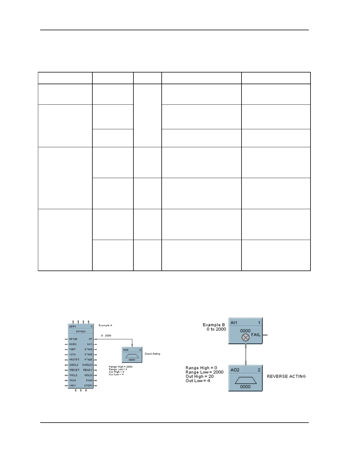
Example
Figure 2-10 shows a Function Block Diagram configuration using an AO function block to retransmit an
analog input value. In example A, the output is from a SPP block to an external controller via the AO block.
In example B, the mA output is 4 mA for an analog input of 2000.
NOTE: Reverse scaling is required for duplex control outputs.
Figure 2-10 AO Function Block Example
 Loading...


