Section VII
g.
Reposition the following front panel controls:
ADAPTIVE
SWEEP
.................
OFF
RESOLUTION BANDWIDTH . . . . . . 100 Hz
FREQ. SPAN/DIV
................
2 KHz
SWEEP
TIME/DIV . . . . . . . . . .
.I
SEC/DIV
h. Check the following:
1.
Collector
of
A3Q4: 10
volts±
.1
volts
2.
Collector
of
A3Ql6:
0.0
volts±
.1
volts
3. A3U5 pin
5:
TTL
LOW
(as measured by logic
clip).
4. A3U5 pins 2, 3, 4, 6 and 9: TTL HIGH (as
measured by logic clip).
5. A3TP2: - .25
volts±
.02 volts.
6.
A3TP3: + .175
volts±
.02 volts.
7. A3U8 pin 6: TTL
HIGH(>
2.0 volts).
i. Manually "clock" SI once and verify that the state
does not change from 100.
j. Short A3TP3 to A3TP4. Verify that the voltage at
A3TP11 can be changed from a negative to positive voltage
by rotating
A3RI4.
Readjust
A3RI4
so the voltage at TPI I
is
at the 0 V transition point. (In some cases it will alternate
between positive and negative.)
k. Check for proper source voltage on A3QI4.
(.I <
vs
< + 4 ).
I.
Readjust
A3RI4*
fully
CCW.
Reposition:
ADAPTIVE
SWEEP
..................
CW
Model 3580A
m. (L)RESP (A3U7 pin 5) should be a TTL HIGH.
Verify
that
any one
of
the following will cause (L)RESP
to
go
LOW.
ADAPTIVE SWEEP
.................
CCW
SWEEP TIME/DIV . . . . . . . . . .05 SEC/DIV
or faster
If
(L)RESP doesn't function properly, check the A8 board.
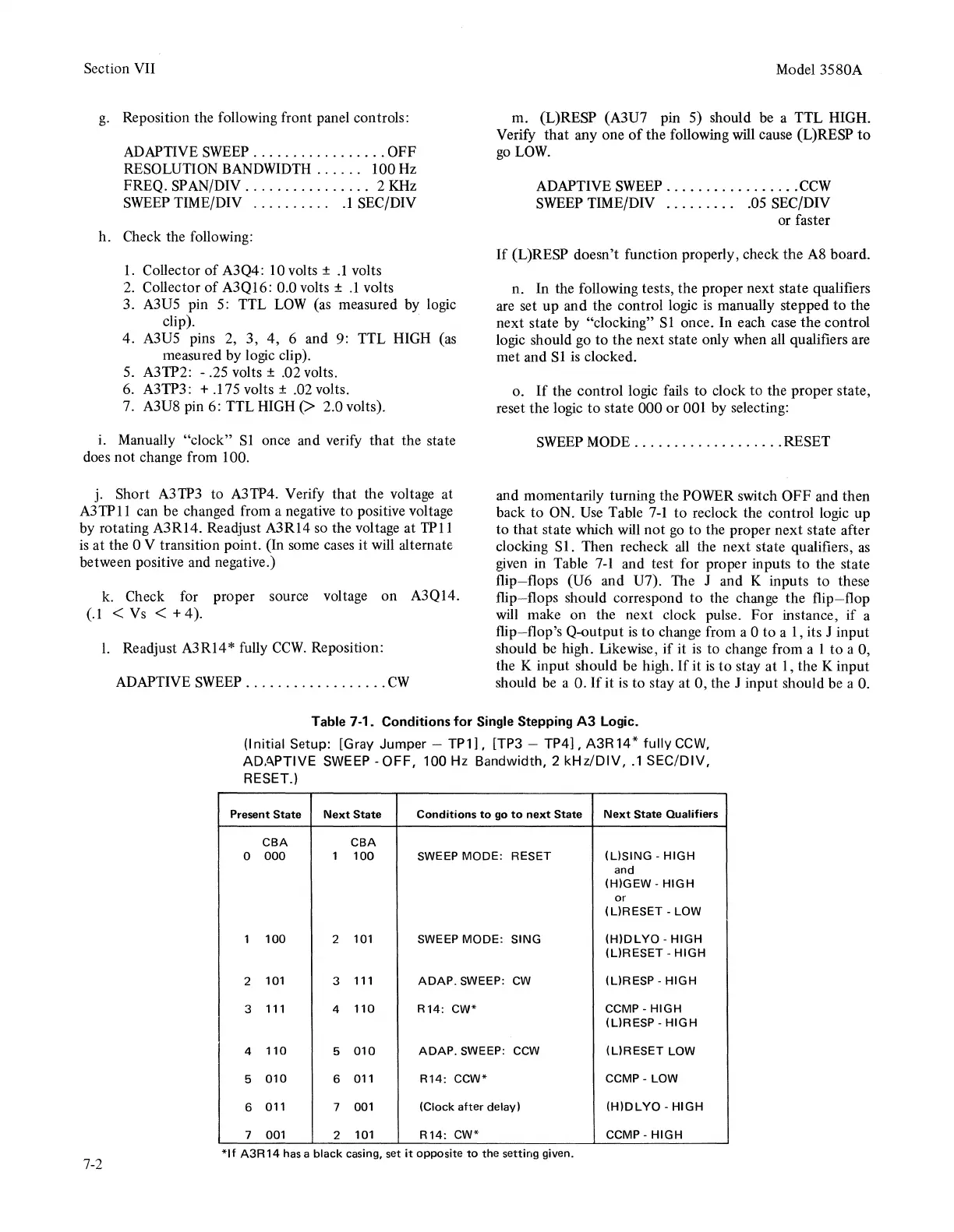
n. In the following tests, the proper next state qualifiers
are set
up
and the control logic
is
manually stepped
to
the
next state by "clocking" SI once. In each case the control
logic should
go
to the next state only when all qualifiers are
met and SI
is
clocked.
o.
If
the control logic fails to clock to the proper state,
reset the logic
to
state 000 or 001 by selecting:
SWEEP
MODE
...................
RESET
and momentarily turning the POWER switch
OFF
and then
back
to
ON. Use Table
7-1
to
reclock the control logic up
to that state which will not
go
to the proper next state after
clocking
Sl.
Then recheck
all
the
next
state qualifiers,
as
given in Table 7-I and test for proper inputs
to
the state
flip-flops (U6 and U7). The J and K inputs
to
these
flip-flops should correspond
to
the change the
flip-flop
will
make
on
the next clock pulse. For instance,
if
a
flip-flop's Q-output
is
to
change from a 0
to
a 1, its J input
should
be
high. Likewise,
if
it
is
to change from a 1 to a 0,
the K input should be high.
If
it
is
to
stay at
I,
the K input
should
be
a
O.
If
it
is
to stay at 0, the J input should be a 0.
Table 7-1. Conditions
for
Single Stepping
A3
Logic.
7-2
(Initial Setup: [Gray Jumper -
TP
1],
[TP3 -
TP4],
A3R 14 *
fully
CCW,
ADAPTIVE
SWEEP
-OFF,
100 Hz Bandwidth, 2
kHz/DIV,
.1
SEC/DIV,
RESET.)
Present State
Next
State
Conditions
to
go
to
next
State
Next
State Qualifiers
CBA
CBA
0
000
1
100
SWEEP
MODE:
RESET
(USING
-
HIGH
and
(H)GEW
-
HIGH
or
(L)RESET
- LOW
1
100
2
101 SWEEP
MODE:
SING
(H)DLYO
-
HIGH
(L)RESET
-
HIGH
2
101
3
111
ADAP.
SWEEP:
cw
(L)RESP
·HIGH
3
111
4
110
R 14:
CW*
CCMP-
HIGH
(L)RESP
-
HIGH
4
110
5
010
ADAP.
SWEEP: ccw
(L)RESET
LOW
5
010
6
011
R14:
CCW*
CCMP-
LOW
6
011
7 001
(Clock
after
delay)
(H)DLYO-
HIGH
7 001
2
101
R 14:
cw•·
CCMP-
HIGH
*If
A3R14
has a
black
casing, set
it
opposite
to
the setting given.