Model 3580A
PERFORMANCE
TESTS
Section V
d. Reposition the following controls:
SWEEP
MODE
....................
SING
e.
After waiting for the sweep to
be
completed
(100 sec.), verify that the noise on the display ± 10
Hz
(± 2 major divisions) away from the 10
KHz
CAL signal (in
center
of
display)
is
at least 70
dB
below the CAL signal.
5-34. Spurious Response Test.
a.
Reposition the following controls:
INPUT SENSITIVITY
.............
- 20
dB
FREQUENCY
..................
00.0 Hz
START-CTR
...................
START
RESOLUTION BANDWIDTH
........
30
Hz
FREQ. SPAN/DIV
................
2
KHz
SWEEP
TIME/DIV . . . . . . . . . . . . . . . 5
SEC
SWEEP
MODE
...................
RESET
b. Momentarily press:
DISPLAY
...............
CLEAR WRITE
c. Adjust ZERO CAL for a peak display on the leftmost
display graticule.
d.
Reposition the following controls:
SWEEP
MODE
.................
MANUAL
and momentarily press:
DISPLAY
...............
CLEAR WRITE
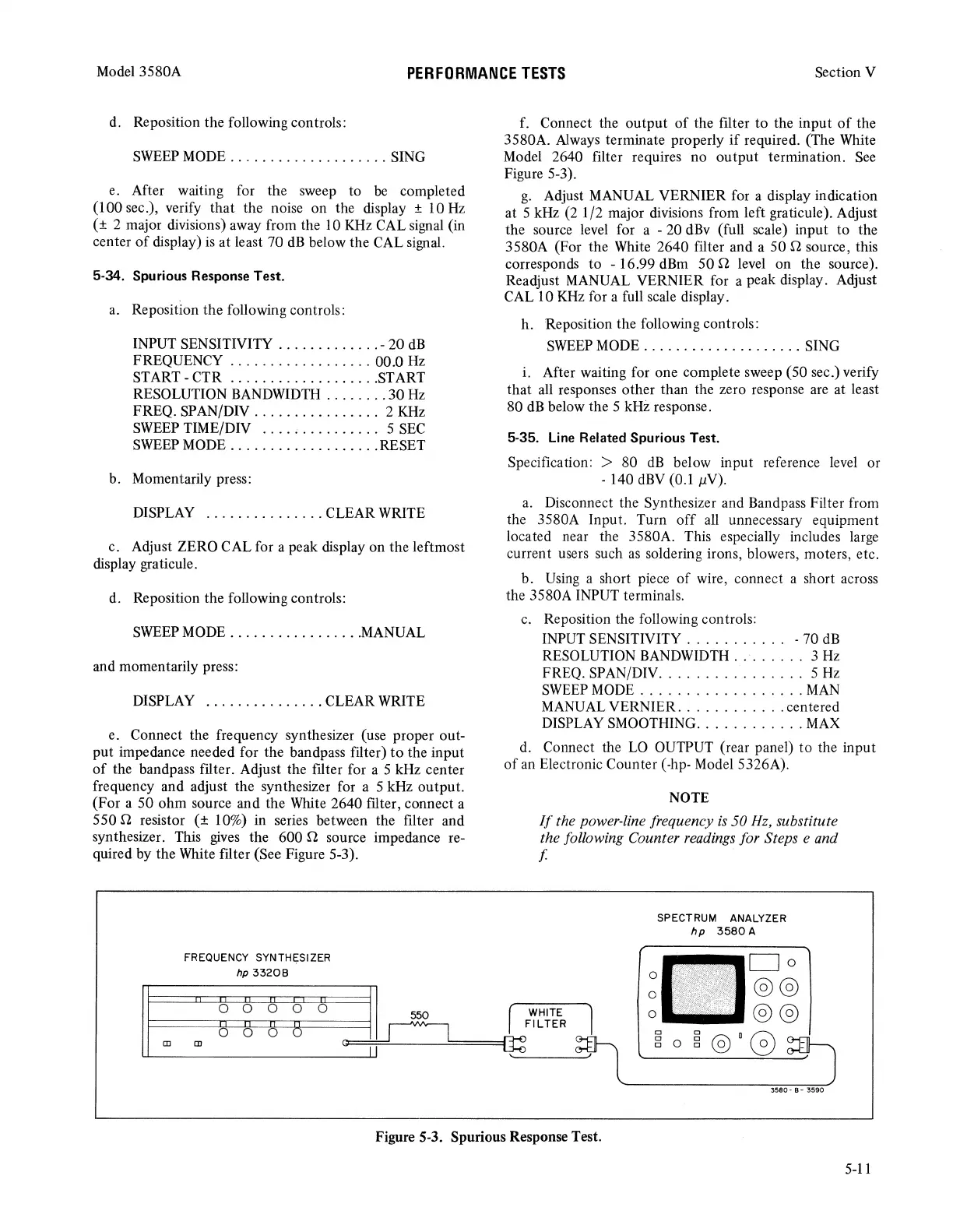
e. Connect the frequency synthesizer (use proper out-
put impedance needed for the bandpass filter)
to
the input
of
the bandpass filter. Adjust the filter for a 5 kHz center
frequency and adjust the synthesizer for a 5 kHz output.
(For a 50 ohm source and the White 2640 filter, connect a
550 n resistor
(±
10%) in series between the filter and
synthesizer. This
gives
the 600 n source impedance re-
quired by the White filter (See Figure 5-3).
FREQUENCY SYNTHl;:SIZER
hp
33208
f. Connect the output
of
the filter
to
the input
of
the
3580A. Always terminate properly
if
required. (The White
Model 2640 filter requires no output termination.
See
Figure 5-3).
g.
Adjust MANUAL VERNIER for a display indication
at 5 kHz
(2
1 /2 major divisions from left graticule). Adjust
the source level for a - 20 dBv (full scale) input
to
the
3580A (For the White 2640 filter and a 50 n source, this
corresponds
to
- 16.99 dBm 50 n level on the source).
Readjust MANUAL VERNIER for a peak display. Adjust
CAL 10
KHz
for a full scale display.
h. Reposition the following controls:
SWEEP
MODE
....................
SING
i. After waiting for one complete sweep (50 sec.) verify
that all responses other than the zero response are at least
80
dB
below the 5 kHz response.
5-35.
Line
Related Spurious Test.
Specification: > 80
dB
below input reference level or
- 140
dBV
(0.1 µV).
a.
Disconnect the Synthesizer and Bandpass Filter from
the 3580A Input. Turn
off
all unnecessary equipment
located near the 3580A. This especially includes large
current users such
as
soldering irons, blowers, moters, etc.
b.
Using
a short piece
of
wire, connect a short across
the 3580A INPUT terminals.
c.
Reposition the following controls:
INPUT SENSITIVITY . . . . . . . . . . . - 70
dB
RESOLUTION BANDWIDTH . . . . . . . . 3
Hz
FREQ. SPAN/DIV
................
5
Hz
SWEEP
MODE
..................
MAN
MANUAL VERNIER. . .
.........
centered
DISPLAY SMOOTHING
............
MAX
d. Connect the
LO
OUTPUT (rear panel)
to
the input
of
an Electronic Counter (-hp- Model 5326A).
NOTE
If
the power-line frequency
is
50 Hz, substitute
the following Counter readings for Steps e and
f
SPECTRUM ANALYZER
hp
3580
A
Figure S-3. Spurious Response Test.
5-11