Model 3580A
frequency from 1
MHz
to 1.5
MHz.
Fine tuning
is
provided
by the error voltage from the VTO Error Amplifier. The
output
of
the VTO
is
applied to a Divide-By-Ten Counter
and to the rear panel L.O. OUTPUT connector. The output
of
the Divide-By-Ten Counter
is
a 100 kHz to 150 kHz
square
wave
which
is
applied to the Input Mixer (A9) and
to the Frequency Discriminator and Tracking Oscillator.
4-101. Frequency Discriminator.
Due
to the inherent non-
linearity
of
the VTO,
an
external frequency control loop
is
required. The frequency control loop
is
comprised
of
a
Frequency Discriminator and VTO Error Amplifier. The
Frequency Discriminator produces a de voltage that
is
linearily proportional to the VTO output frequency. This
de
voltage
is
applied to the non-inverting port
of
the
VTO
Error Amplifier where it
is
compared to the reference
voltage at the inverting port.
Any
difference between these
two voltages causes the output
of
the Error Amplifier to
increase or decrease to correct the VTO frequency.
4-102. The 100
kHz
to 150 kHz VTO output
signal
is
applied to a Divide-By-Ten Counter in the Frequency
Discriminator. The output
of
the Divide-By-Ten Counter
is
a 10
kHz
to
15
kHz square
wave
which positive-edge
triggers the Precision Monostable Multivibrator.
When
triggered, the output
of
the Monostable Multivibrator
goes
high for exactly 50 µsec. This gates
off
the Current Sink
allowing
C21
to charge toward+ 10 V through R37.
At
the
end
of
the 50 µsec. charge period, the Current Sink
is
gated
on causing
C21
to discharge at a fixed rate.
As
the
VTO
frequency increases, the charge period
of
C21
remains at
50 µsec. but the discharge period becomes shorter.
As
a
result, the
average
charge on
C21
increases. The voltage
across
C21
is
amplified, filtered and applied to the
non-inverting port
of
the
VTO
Error Amplifier. This voltage
varies from 0 V to + 6 V
de
as
the VTO frequency
is
tuned
from 100 kHz
to
150 kHz.
4-103. Precision Monostable Multivibrator. The magnitude
of
the
de
voltage at the output of the Frequency
Discriminator
is
determined by the duty cycle
of
the pulse
generated by the Precision Monostable Multivibrator. In
order for the output voltage
to
increase linearily with
frequency, the width
of
the positive half cycle
of
the pulse
must be constant regardless
of
frequency and the width
of
the negative half cycle must vary linearily with frequency.
This requires precise timing and a high degree
of
stability
not obtainable with conventional R/C-coupled "one-shot"
multivibrators.
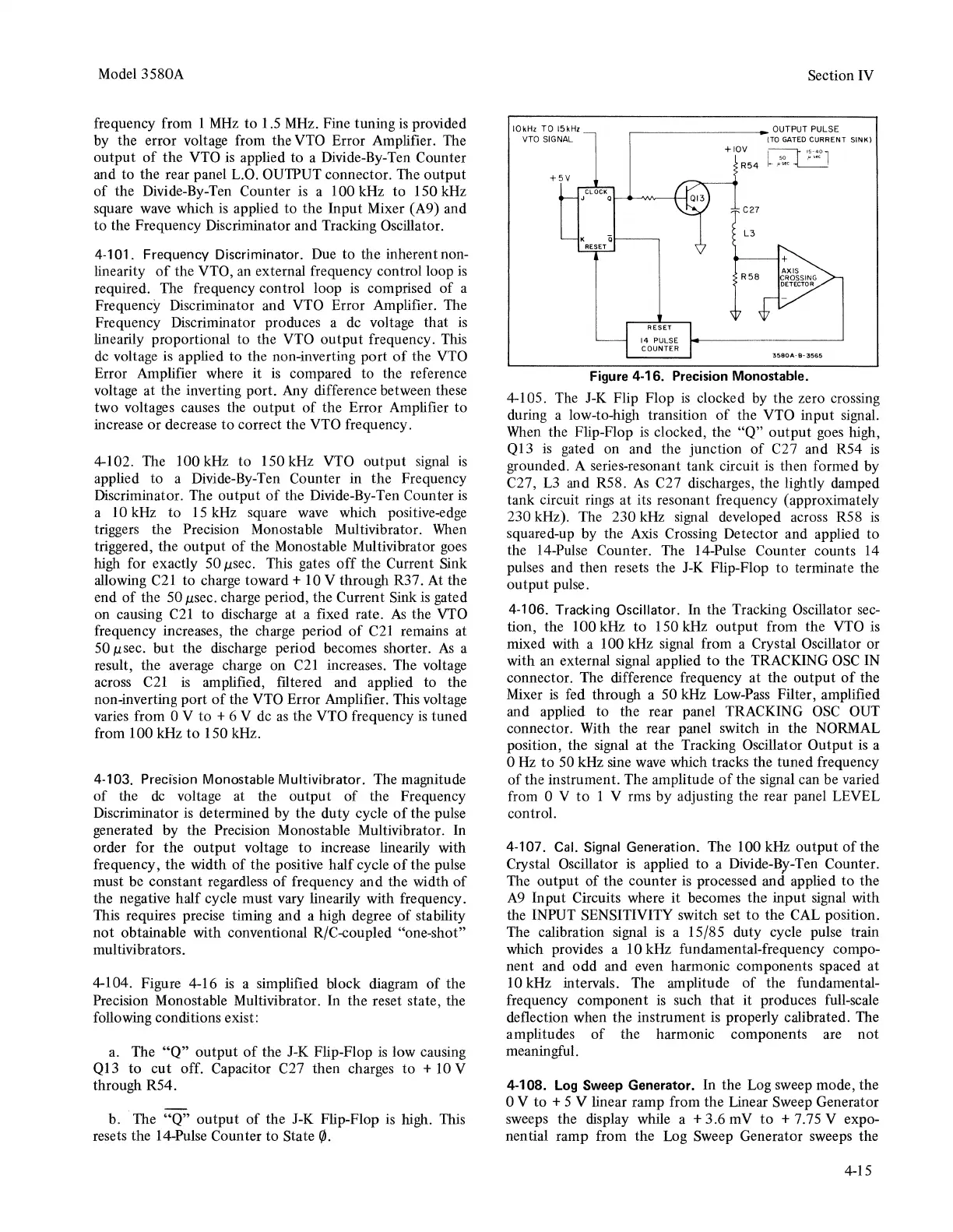
4-104. Figure 4-16
is
a simplified block diagram
of
the
Precision Monostable Multivibrator. In the reset state, the
following conditions exist:
a.
The
"Q"
output
of
the J-K Flip-Flop
is
low causing
Q13
to cut off. Capacitor C27 then charges
to
+ 10 V
through R54.
b. The
"Q"
output
of
the J-K Flip-Flop
is
high. This
resets the 14-Pulse Counter to State
f/J.
IOkHz TO
15kHz
VTO
SIGNAL
Section
IV
~-------OUTPUT
PULSE
RESET
14
PULSE
COUNTER
+IOV
R54
C27
L3
{TO
GATED
CURRENT SINK)
'3580A·B~3565
Figure 4-16. Precision Monostable.
4-105.
The
J-K Flip Flop
is
clocked
by
the zero crossing
during a low-to-high transition
of
the VTO input signal.
When
the Flip-Flop
is
clocked, the
"Q"
output
goes
high,
Ql3
is
gated on and the junction
of
C27 and R54
is
grounded. A series-resonant tank circuit
is
then formed
by
C27,
L3
and R58.
As
C27 discharges, the lightly damped
tank circuit rings at its resonant frequency (approximately
230 kHz). The 230 kHz signal developed across R58
is
squared-up by the
Axis
Crossing Detector and applied to
the 14-Pulse Counter. The 14-Pulse Counter counts
14
pulses and then resets the
J-K
Flip-Flop to terminate the
output pulse.
4-106. Tracking Oscillator. In the Tracking Oscillator
sec-
tion, the 100 kHz to 150
kHz
output from the
VTO
is
mixed with a 100 kHz signal from a Crystal Oscillator or
with
an
external signal applied
to
the TRACKING
OSC
IN
connector. The difference frequency at the output
of
the
Mixer
is
fed through a 50 kHz
Low-Pass
Filter, amplified
and applied to the rear panel TRACKING
OSC
OUT
connector. With the rear panel switch in the NORMAL
position, the signal at the Tracking Oscillator Output
is
a
0
Hz
to
50
kHz sine
wave
which tracks the tuned frequency
of
the instrument. The amplitude
of
the signal can be varied
from 0 V
to
1 V rms by adjusting the rear panel LEVEL
control.
4-107.
Cal.
Signal
Generation. The 100 kHz output
of
the
Crystal Oscillator
is
applied to a Divide-By-Ten Counter.
The output of the counter
is
processed and applied to the
A9
Input Circuits where it becomes the input signal with
the INPUT SENSITIVITY switch set
to
the CAL position.
The calibration signal
is
a 15/85 duty cycle pulse train
which provides a 10 kHz fundamental-frequency compo-
nent and odd and even harmonic components spaced at
10
kHz intervals. The amplitude
of
the fundamental-
frequency component
is
such that it produces full-scale
deflection when the instrument
is
properly calibrated. The
amplitudes
of
the harmonic components are not
meaningful.
4-108.
Log
Sweep Generator. In the Log sweep mode, the
0 V to + 5 V linear ramp from the Linear Sweep Generator
sweeps the display while a + 3.6 mV
to
+ 7.75 V expo-
nential ramp from the Log Sweep Generator sweeps the
4-15