Model 3580A
PERFORMANCE
TESTS
Section V
b.
By
alternately pressing and releasing DISPLAY -
CLEAR
WRITE
while adjusting MANUAL VERNIER,
center the display indication (a narrow spike).
c. Connect a properly terminated frequency synthesizer
to the input
of
the 3580A. Adjust the synthesizer for a
10
kHz
- 20
dBv
signal
(- 20
dBm
900 n for Option 002)
output. (See Table 5-3.) Momentarily press DISPLAY -
CLEAR WRITE.
d.
Adjust the FREQUENCY dial (pulled out for fine
tuning) for a peak display indication.
e.
Reposition the following front panel controls:
AMPLITUDE
MODE
........
LOG
1 dB/DIV
f. Readjust the FREQUENCY
dial
(fine tune position)
for a peak display indication
of
the
IO
KHz
input. Adjust
CAL
10
KHz
for a full scale 0
dB
display, if not already
so
adjusted.
g.
Slowly rotate MANUAL VERNIER
CW
until the
display dot
has
dropped 3
dB
in amplitude. (Remember,
the display
is
calibrated 1 dB/DIV). This
is
the upper 3
dB
point
of
the filter.
h. Momentarily press DISPLAY - CLEAR WRITE.
Slowly increase the frequency
of
the source. The dot
will
move
to a full
scale
display and then down to the lower
3
dB
point
of
the filter.
i.
Note the frequency
of
the source at this lower 3
dB
point_
Hz.
This frequency,
less
the orfginal
IO
KHz
start
frequency,
is
the 3
dB
bandwidth
of
the 300
Hz
filter.
It
should
be
300
Hz
± 45 Hz.
j. Repeat Steps f through i for the
IOO
Hz, 30
Hz
and
10
Hz
filters.
See
Table
5-11
for the start frequency
of
the
source, FREQUENCY dial setting, RESOLUTION
BAND-
WIDTH,
FREQ. SPAN/DIV, and the test limits.
At
the start
of each new bandwidth setting, always center the display
with
MANUAL
VERNIER, and adjust the FREQUENCY
dial, and CAL
IO
KHz
for a full scale, peak display at the
appropriate start frequency. Then make the appropriate
adjustments for the upper and lower 3
dB
points.
Table 5-11.
300
Hz
thru
10
Hz
Bandwidth Tests.
SOURCE
START
RESOLUTION
FREQ.
SPAN/DIV
3
dB
BANDPASS
FREQ.
and
3580A
BANDWIDTH
TEST
LIMITS
FREQUENCY
10
kHz
300 Hz
50
Hz
300 Hz ±
45
Hz
1
kHz
100
Hz
50
Hz
100
Hz ±
15
Hz
1
kHz
30
Hz
10
Hz
30 Hz ± 4.5 Hz
1
kHz
10
Hz
5
Hz
10 Hz ±
1.5
Hz
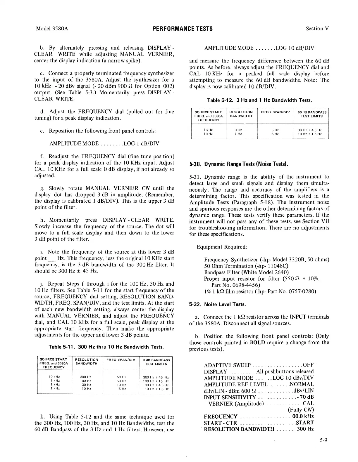
k.
Using
Table 5-12 and the same technique used for
the 300 Hz, 100 Hz, 30
Hz,
and 10
Hz
Bandwidths, test the
60
dB
Bandpass
of
the 3
Hz
and 1
Hz
filters. However,
use
AMPLITUDE
MODE
.......
LOG
10
dB/DIV
and measure the frequency difference between the
60
dB
points.
As
before, always adjust the FREQUENCY
dial
and
CAL
10
KHz
for a peaked
full
scale
display before
attempting to measure the 60
dB
bandwidths. Note: The
display
is
now calibrated 10 dB/DIV.
Table 5-12. 3
Hz
and 1
Hz
Bandwidth Tests.
SOURCE
START
RESOLUTION
FREQ.
SPAN/DIV
60
dB
BANDPASS
FREQ.
and
3580A
BANDWIDTH
TEST
LIMITS
FREQUENCY
1
kHz
3 Hz 5 Hz
30 Hz ± 4.5 Hz
1
kHz
1 Hz
5 Hz
10
Hz
±
1.5
Hz
5-30.
Dynamic
Range
Tests
(Noise
Tests).
5-31. Dynamic range
is
the ability
of
the instrument to
detect
large
and small signals and display them simulta-
neously.
The
range and accuracy
of
the amplifiers
is
a
determining factor. This specification
was
tested in the
Amplitude Tests (Paragraph 5-18). The instrument noise
and spurious responses are the other determining factors of
dynamic range. These tests verify these parameters.
If
the
instrument will not pass any
of
these tests,
see
Section VII
for troubleshooting information. There
are
no adjustments
for these specifications.
Equipment Required:
Frequency Synthesizer (-hp- Model 3320B, 50 ohms)
50 Ohm Termination (-hp- 1 I048C)
Bandpass Filter (White Model 2640)
Proper input resistor for filter (550 n ±
IO%,
Part No.
06984456)
1 % 1
kn
film resistor (-hp- Part No. 0757-0280)
5-32. Noise Level Tests.
a.
Connect the 1
kn
resistor across the INPUT terminals
of
the 3580A. Disconnect all signal sources.
b. Position the following front panel controls: (Only
those controls printed
in
BOLD require a change from the
previous tests).
ADAPTIVE
SWEEP
.................
OFF
DISPLAY
........
All
pushbuttons released
AMPLITUDE
MODE
......
LOG 10 dBv/DIV
AMPLITUDE
REF LEVEL
.......
NORMAL
dBv/LIN - dBm 600 n
............
dBv/LIN
INPUT SENSITIVITY
.............
-
70
dB
VERNIER (Amplitude) . . . . . . . . . . . CAL
(Fully
CW)
FREQUENCY
.................
00.0 kHz
START-CTR
...................
START
RESOLUTION BANDWIDTH . . . . . .
300
Hz
5-9