Model 3580A
GAIN CONTROL
~IHz
GAIN
ADJ
RI
~3Hz
GAIN
ADJ
R2
~
IOHz
GAIN
TPI
ADJ
IOOkHz
R3
INPUT
~
30Hz
FROM
GAIN
IF
ADJ
FILTER
R4
~IOOHz
GAIN
ADJ
CR2
R5
CR3
RIG
300Hz
IOOHz
30Hz IOHz
35SOA -
B-
3549
BANDWIDTH LINES
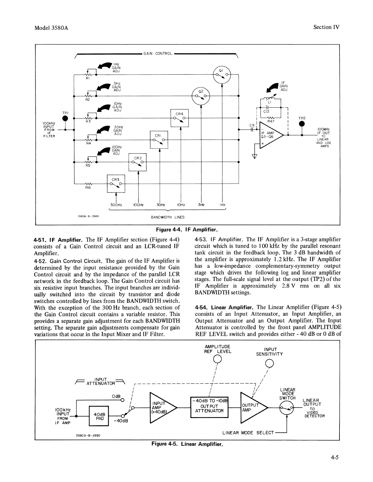
Figure
4-4.
4-51.
IF
Amplifier. The IF Amplifier section (Figure 4-4)
consists
of
a
Gain
Control circuit and an LCR-tuned IF
Amplifier.
4-52.
Gain
Control Circuit. The
gain
of
the IF Amplifier
is
determined by the input resistance provided by the Gain
Control circuit and by the impedance
of
the parallel LCR
network in the feedback loop. The Gain Control circuit has
six resistive input branches. The input branches
are
individ-
ually switched into the circuit by transistor and diode
switches controlled by lines from the
BANDWIDTH
switch.
With
the exception
of
the 300
Hz
branch, each section
of
the Gain Control circuit contains a variable resistor. This
provides a separate
gain
adjustment for each
BANDWIDTH
setting. The separate gain adjustments compensate for
gain
variations that occur in the Input Mixer and IF Filter.
INPUT
Section IV
IF
,.GAIN
ADJ
:fB
i
I I
TP2
I R47 I
C9 I
I
IOOkHz
IF
OUT
TO
LINEAR
AND
LOG
AMPS
3Hz I
Hz
IF
Amplifier.
4-53. IF Amplifier. The IF Amplifier
is
a 3-stage amplifier
circuit which
is
tuned to 100 kHz by the parallel resonant
tank circuit in the feedback loop. The 3
dB
bandwidth
of
the amplifier
is
approximately 1.2 kHz. The IF Amplifier
has a low-impedance complementary-symmetry output
stage which
drives
the following log and linear amplifier
stages. The full-scale
signal
level at the output (TP2)
of
the
IF Amplifier
is
approximately 2.8 V rms on
all
six
BANDWIDTH
settings.
4-54.
Linear
Amplifier. The Linear Amplifier (Figure 4-5)
consists of an Input Attenuator, an Input Amplifier, an
Output Attenuator and
an
Output Amplifier. The Input
Attenuator
is
controlled by the front panel AMPLITUDE
REF LEVEL switch and provides either - 40
dB
or 0
dB
of
AMPLITUDE INPUT
REF
LEVEL SENSITIVITY
y 0
I I
I I
I I
F
ATTENUATOR=\
r---------------1--------7
I
I I I I
IOOkHz
I NPUT---110-----1
FROM
IF
AMP
3580A-B-3550
OdB
I I I I
I
~
I
I
'n-----1
-40dB
TO-IOdB
OUTPUT
ATTENUATOR
LINEAR
MODE
SELECT
Figure
4·5.
Linear
Amplifier.
4-5