Section III
GENERAL
OPERATING
INFORMATION
Model 3580A
3-13.
Input
Impedance.
3-14. The input impedance
of
the 3580A
is
1 megohm
shunted
by
30
pF (28 pF nominal).
This
high input
impedance has a minimum loading effect on the input
signal
and further permits the use
of
a
10
megohm, 10 pF
Voltage Divider Probe (-hp- 10004B).
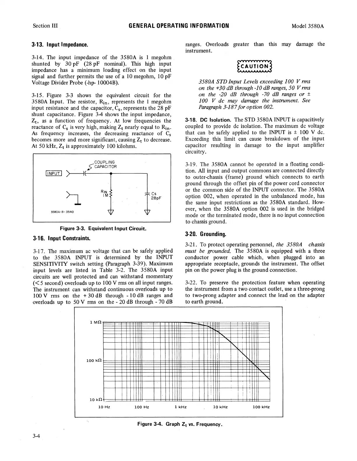
3-15. Figure
3-3
shows the equivalent circuit for the
3580A Input. The resistor, Rin, represents the 1 megohm
input resistance and the capacitor, C
5
, represents the 28 pF
shunt capacitance. Figure
3-4
shows
the input impedance,
Zt,
as
a function
of
frequency.
At
low frequencies the
reactance
of
C
5
is
very high, making Zt nearly equal to Rin.
As
frequency increases, the decreasing reactance
of
C
5
becomes more and more significant, causing Zt to decrease.
At
50 kHz, Zt
is
approximately 100 kilohms.
COUPLING
C-
CAPACITOR
!INPUT!
~~~~~~----<--~~~~
3580A-B-3540
RIN
>
IM5
Tes
~28pF
Figure 3-3. Equivalent Input Circuit.
3-16.
Input
Constraints.
3-17.
The
maximum
ac
voltage that can
be
safely applied
to the 3580A
INPUT
is
determined by the INPUT
SENSITIVITY switch setting (Paragraph 3-39). Maximum
input levels are listed in Table 3-2. The 3580A input
circuits are
well
protected and can withstand momentary
( < 5 second) overloads up to 100 V
rms
on all input ranges.
The
instrument can withstand continuous overloads up
to
100 V rms on the + 30
dB
through - 10
dB
ranges and
overloads up to 50 V rms on the - 20
dB
through - 70 dB
1
Mfi
=
100
kfi
10
kfi
10
Hz
100
Hz
ranges. Overloads greater than this
may
damage the
instrument.
3580A STD Input Levels exceeding 100 V rms
on
the
+30
dB through -10 dB
ranges,
50 Vrms
on the -20
dB
through -
70
dB
ranges
or ±
100 V de may
damage
the instrument. See
Paragraph
3-187 for option 002.
3-18.
DC
Isolation. The
STD
3580A
INPUT
is
capacitively
coupled to provide
de
isolation. The maximum
de
voltage
that can
be
safely applied to the
INPUT
is
± 100 V de.
Exceeding this limit can
cause
breakdown
of
the input
capacitor resulting in damage to the input amplifier
circuitry.
3-19.
The
3580A cannot be operated in a floating condi-
tion.
All
input and output commons are connected directly
to outer-chassis (frame) ground which connects to earth
ground through the offset pin
of
the power cord connector
or the common side
of
the
INPUT
connector. The 3580A
option 002, when operated in the unbalanced mode, has
the
same
input restrictions
as
the 3580A standard.
How-
ever, when the 3580A option 002
is
used in the bridged
mode or the terminated mode, there
is
no input connection
to chassis ground.
3-20.
Grounding.
3-21.
To
protect operating personnel, the 3580A chassis
must be grounded. The 3580A
is
equipped with a three
conductor power cable which, when plugged into
an
appropriate receptacle, grounds the instrument. The offset
pin on the power plug
is
the ground connection.
3-22.
To
preserve the protection feature when operating
the instrument from a two contact outlet,
use
a three-prong
to two-prong adapter and connect the lead on the adapter
to earth ground.
:
"S.:
'
'
'~
'
'
I
I
I
~~
! I
'
'
""'"
I
'
l
"l
T
!
I
T
T
:
!
1
kHz
10
kHz
100
kHz
Figure 3-4.
Graph
Zt
vs.
Frequency.
3-4