Section V
ADJUSTMENT
PROCEDURES
Model 3580A
d. Reposition the following front panel controls:
FREQUENCY
.................
05.0 kHz
SWEEP
MODE
.................
MANUAL
e. Adjust the rear panel TRACKING
OSC
LEVEL fully
CW,
and set the EXT REF - NORMAL switch
to
NORMAL.
f. Connect the oscilloscope
to
the rear panel TRACK-
ING
OSC
OUT connector and monitor the output.
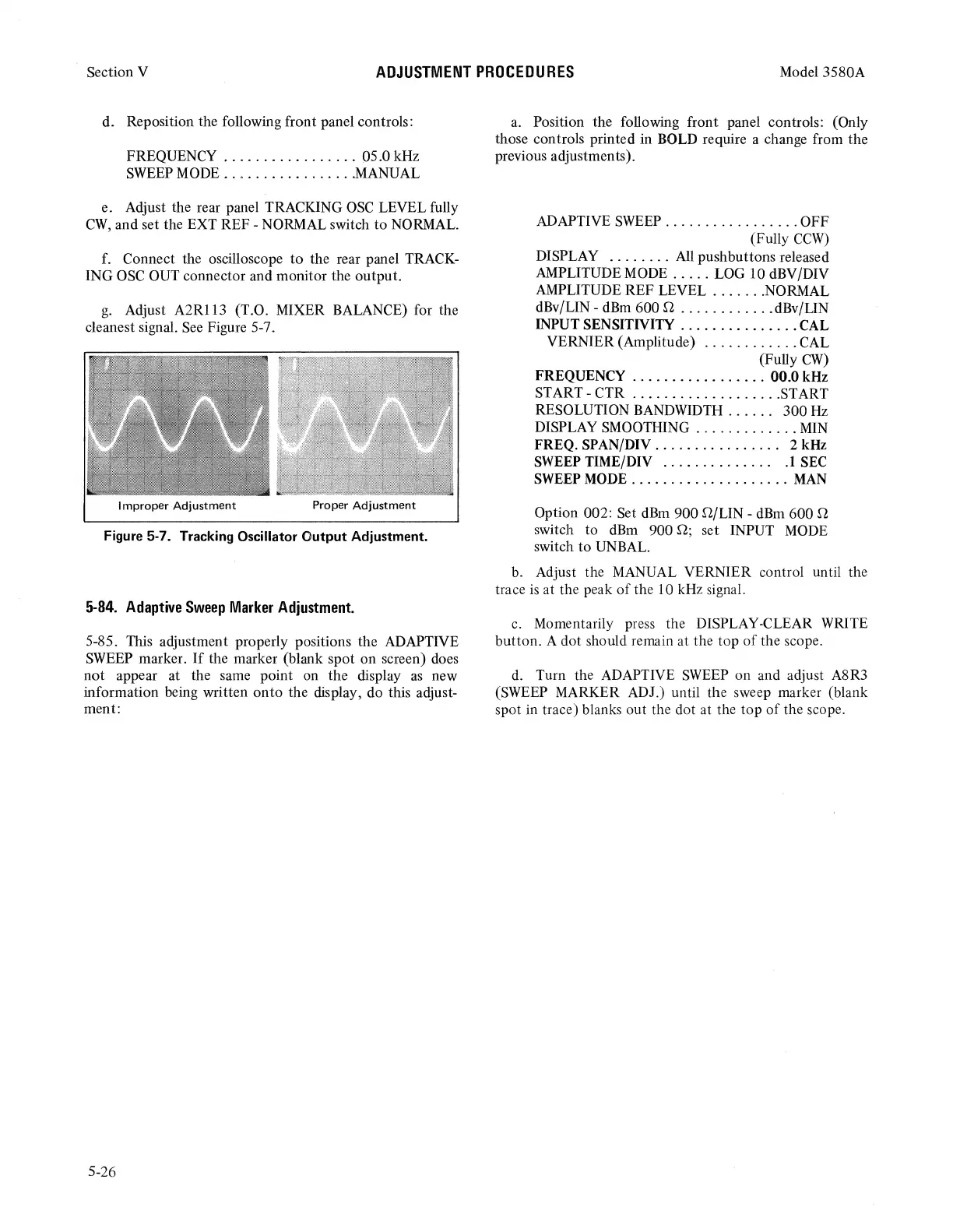
g.
Adjust
A2Rl13
(T.O. MIXER BALANCE) for the
cleanest signal.
See
Figure
5-
7.
Improper
Adjustment
Proper
Adjustment
Figure 5-7. Tracking Oscillator
Output
Adjustment.
5-84.
Adaptive
Sweep
Marker
Adjustment.
5-85. This adjustment properly positions the ADAPTIVE
SWEEP
marker.
If
the marker (blank spot on screen) does
not
appear at the same point on the display
as
new
information being written
onto
the display, do this adjust-
ment:
5-26
a.
Position the following front panel controls: (Only
those controls printed in BOLD require a change from the
previous adjustments).
ADAPTIVE
SWEEP
.................
OFF
(Fully
CCW)
DISPLAY
........
All
pushbuttons released
AMPLITUDE
MODE
.....
LOG 10 dBV/DIV
AMPLITUDE REF LEVEL
.......
NORMAL
dBv/LIN - dBm 600 Q
............
dBv/LIN
INPUT SENSITNITY
...............
CAL
VERNIER (Amplitude)
............
CAL
(Fully
CW)
FREQUENCY
.................
00.0 kHz
START-CTR
...................
START
RESOLUTION BANDWIDTH . . . . . . 300
Hz
DISPLAY SMOOTHING
.............
MIN
FREQ. SPAN/DIV
................
2 kHz
SWEEP
TIME/DIV . . . . . . . . . . . . . .
.1
SEC
SWEEP
MODE
....................
MAN
Option 002: Set
dBm
900 Q/LIN - dBm 600 Q
switch
to
dBm
900 D; set INPUT
MODE
switch
to
UNBAL.
b.
Adjust the MANUAL VERNIER control until the
trace
is
at the peak
of
the 10 kHz signal.
c.
Momentarily press the DISPLAY-CLEAR WRITE
button. A dot should remain at the top
of
the scope.
d.
Turn the ADAPTIVE
SWEEP
on and adjust A8R3
(SWEEP MARKER ADJ.) until the sweep marker (blank
spot in trace) blanks out the dot at the
top
of
the scope.