Model 3580A
GENERAL
OPERATING
INFORMATION
Section III
3-23. For battery powered instruments (Option 001), the
common binding post
of
the INPUT connector (Case
Ground
¢"
) should be connected
to
earth ground or
to
an appropriate system ground.
If
a system ground
is
used,
extra
care
should
be
taken to ensure that
it
is
actually at
ground potential and
is
not
a voltage source.
3-24.
Ground
Loops.
3-25. In the design
of
the 3580A, extra care has been taken
to
control internal ground currents
that
could produce
undesirable responses or degrade the accuracy
of
low level
measurements. Due
to
its wide dynamic range and high
sensitivity, however, the 3580A can be affected by external
ground currents or "ground loops" which are normally
caused by poor grounding. The following paragraphs briefly
describe the common power-line ground loop and outline
the steps
that
can be taken
to
minimize ground loop
problems.
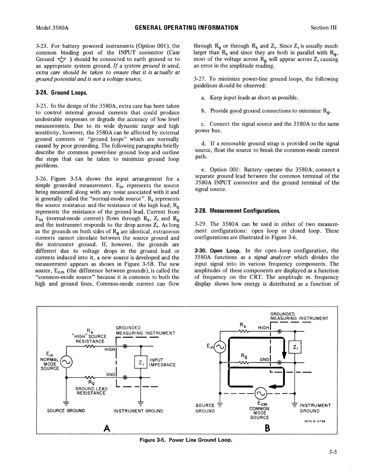
3-26. Figure 3-5A shows the input arrangement for a
simple grounded measurement.
Ein
represents the source
being measured along with any noise associated with
it
and
is
generally called the "normal-mode source".
Rs
represents
the source resistance and the resistance
of
the high lead;
Rg
represents the resistance
of
the ground lead. Current from
Ein (normal-mode current) flows through
Rs,
Z
1
and
Rg
and the instrument responds
to
the drop across Z
1
•
As
long
as
the grounds on
both
sides
of
Rg
are identical, extraneous
currents cannot circulate between the source ground and
the instrument ground.
If,
however, the grounds are
different due
to
voltage drops in the ground lead or
currents induced
into
it,
a new source is developed and the
measurement appears
as
shown in Figure 3-5B. The new
source,
Ecm
(the difference between grounds),
is
called the
"common-mode source" because it
is
common
to
both
the
high and ground lines. Common-mode current can flow
Ein
NORMAL
MODE
SOURCE
Rs
"HIGH"
SOURCE
Rg
GROUND LEAD
RESISTANCE
SOURCE
GROUND
A
INPUT
z,
IMPEDANCE
INSTRUMENT
GROUND
through
Rg
or through
Rs
and Z
1
• Since Z
1
is usually much
larger than
Rs
and since they are both in parallel with
Rg,
most
of
the voltage across
Rg
will appear across Z
1
causing
an error in the amplitude reading.
3-27. To minimize power-line ground loops, the following
guidelines should be observed:
a.
Keep input leads as short
as
possible.
b. Provide good ground connections
to
minimize
Rg.
c. Connect the signal source and the 3580A
to
the same
power bus.
d.
If
a removable ground strap
is
provided
on
the signal
source, float the source
to
break the common-mode current
path.
e. Option 001: Battery operate the 3580A; connect a
separate ground lead between the common terminal
of
the
3580A INPUT connector and the ground terminal
of
the
signal source.
3-28.
Measurement
Configurations.
3-29. The 3580A can
be
used in either
of
two measure-
ment configurations: open loop or closed loop. These
configurations are illustrated in Figure 3-6.
3-30.
Open
Loop. In the open-loop configuration, the
3580A functions
as
a
signal
analyzer which divides the
input signal into its various frequency components. The
amplitudes
of
these components are displayed
as
a function
of
frequency on the CRT. The amplitupe
vs.
frequency
display shows how energy
is
distributed
as
a function
of
SOURCE
-:;:-
GROUND
GROUNDED
MEASURING INSTRUMENT
HIGHr--
-
I •
I
Rg
j '
•
I
j---
----6)---
Ecm
COMMON
MODE
SOURCE
B
-:;:-
INSTRUMENT
GROUND
3!575-B-2738
Figure 3-5. Power Line Ground Loop.
3-5