Model 3580A
LOG
AMPLIFIER
DIFFERENTIAL
PAIR
Vo
+15V
----,
I
I
I
Ve I
I
I
I
I
I
I
-6V
I
L
_________
J
CONSTANT
CURRENT
SOURCE
(LOG
SCALE)
---1-----------V1N
3580A-
B--
3602
Figure
4-7. Typical
Log
Amplifier Stage.
b.
When
the input signal
is
above the range
of
a
given
stage, that stage will make a constant contribution
to
the
output
of
the log amplifier.
c.
When
the input signal
is
within the range
of
a
given
stage, that stage provides the logarithmic output over a
10
dB
range. The logarithmic output
is
added
to
the
constant output
of
the more sensitive stages.
4-58. Since there are twelve 10
dB
stages in the log
amplifier package, it would appear that the overall dynamic
range
is
120 dB.
In
practice, however, the first and last
stages
do
not produce usable outputs over their entire
range. The dynamic range
of
the
device
is
therefore limited
to
approximately 100
dB.
The 3580A input
levels
are such
that only 80
dB
to
90
dB
of
the 100
dB
range
is
used.
4-59. Video Detector. The Video Detector
is
an
average-
responding, active, full-wave detector circuit which pro-
duces a de voltage proportional
to
the amplitude
of
the log
or linear IF signal. The output
of
the Video Detector,
ranging from 0 V to +2.5 V de full scale,
is
applied
to
the
Video Filter.
4-60. Video Filter. The purpose
of
the Video filter
is
to
smooth out the ripple and random noise riding on the
Section IV
detected video signal. The filter consists
of
a single-pole
RC
network followed by
an
output buffer. The response
of
the
filter
is
varied by changing the values
of
the
RC
elements in
the circuit. The amount
of
filtering
is
increased
as
the
BANDWIDTH
setting
is
narrowed or
as
the DISPLAY
SMOOTHING
control
is
varied from
MIN
to
MAX.
STAGE
;i,
4o2V
7
8
9~
~
3.2v
4-~,,__
__
1.2v
o.12v
32uV
~I0.32mV
3.2mV
32m~0.32V
o2V
3580A
RANGE
-80d8
OdB
(0.23mV I (2.3V)
INPUT
LEVEL
3580A-B-3603
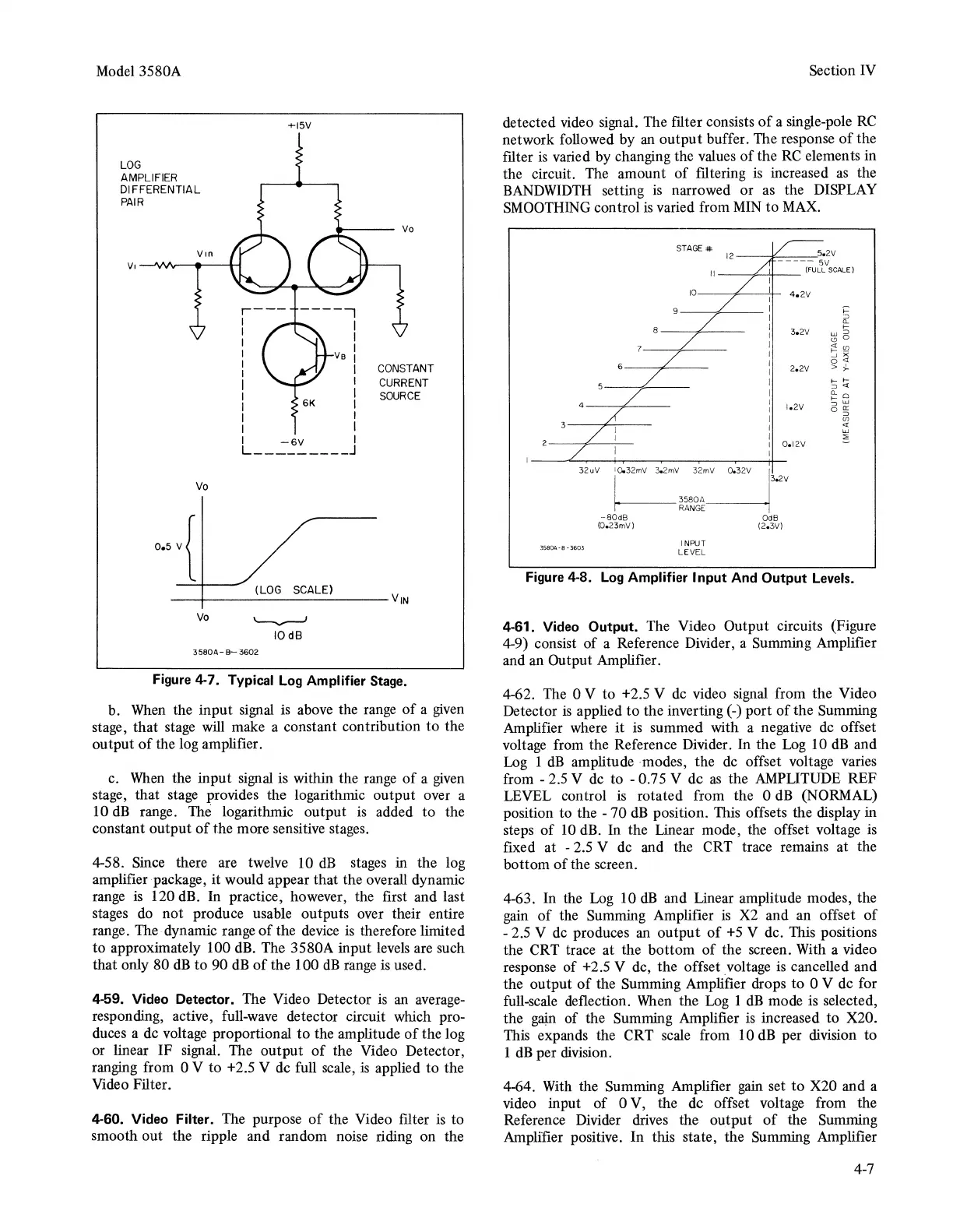
Figure
4-8.
Log
Amplifier Input And Output Levels.
4-61. Video Output. The Video Output circuits (Figure
4-9) consist of a Reference Divider, a Summing Amplifier
and an Output Amplifier.
4-62. The 0 V to +2.5 V
de
video signal from the Video
Detector
is
applied to the inverting(-) port
of
the Summing
Amplifier where it
is
summed with a negative de offset
voltage from the Reference Divider. In the
Log
10
dB
and
Log 1
dB
amplitude modes, the
de
offset voltage varies
from - 2.5 V de to - 0.75 V de
as
the AMPLITUDE REF
LEVEL control
is
rotated from the 0
dB
(NORMAL)
position to the - 70
dB
position. This offsets the display in
steps
of
10
dB. In the Linear mode, the offset voltage
is
fixed at - 2.5 V de and the CRT trace remains at the
bottom
of
the screen.
4-63. In the
Log
10
dB
and Linear amplitude modes, the
gain
of
the Summing Amplifier
is
X2
and an offset
of
- 2.5 V de produces
an
output
of
+5
V de. This positions
the CRT trace at the bottom
of
the screen. With a video
response of +2.5 V de, the offset
_voltage
is
cancelled and
the output
of
the Summing Amplifier drops to 0 V de for
full-scale deflection.
When
the
Log
1
dB
mode
is
selected,
the
gaj.n
of the Summing Amplifier
is
increased to X20.
This expands the CRT scale from 10
dB
per division to
1
dB
per division.
4-64. With the Summing Amplifier
gain
set
to
X20 and a
video input
of
0 V, the de offset voltage from the
Reference Divider drives the output
of
the Summing
Amplifier positive.
In
this state, the Summing Amplifier
4-7