Section V
PERFORMANCE
TESTS
Model 3580A
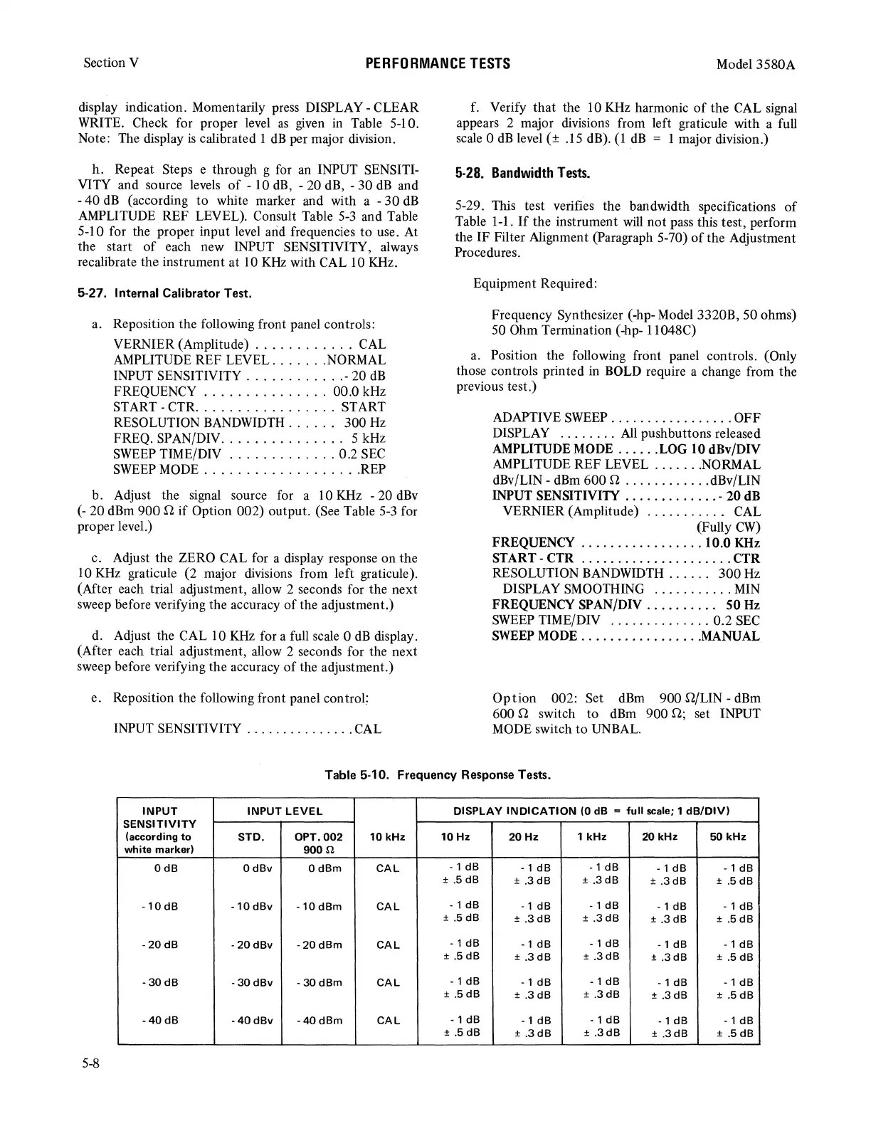
display indication. Momentarily press DISPLAY - CLEAR
WRITE. Check for proper level
as
given
in
Table 5-10.
Note: The display
is
calibrated 1
dB
per major division.
h.
Repeat Steps e through g for an INPUT SENSITI-
VITY and source levels
of
- 10
dB,
- 20 dB, -
30
dB
and
- 40
dB
(according
to
white marker and with a -
30
dB
AMPLITUDE REF LEVEL). Consult Table
5-3
and Table
5-10 for the proper input level arid frequencies
to
use. At
the start
of
each new INPUT SENSITIVITY, always
recalibrate the instrument at 10
KHz
with CAL 10 KHz.
5-27. Internal Calibrator Test.
a. Reposition the following front panel controls:
VERNIER (Amplitude)
............
CAL
AMPLITUDE REF LEVEL
.......
NORMAL
INPUT SENSITIVITY
............
- 20
dB
FREQUENCY
...............
00.0 kHz
START-CTR
.................
START
RESOLUTION
BANDWIDTH
......
300
Hz
FREQ. SPAN/DIV
...............
5 kHz
SWEEP
TIME/DIV
.............
0.2
SEC
SWEEP
MODE
...................
REP
b. Adjust the signal source for a 10 KHz - 20
dBv
(-
20 dBm 900 Q
if
Option 002) output. (See Table
5-3
for
proper level.)
c. Adjust the ZERO CAL for a display response on the
10
KHz
graticule (2 major divisions from left graticule).
(After each trial adjustment, allow 2 seconds for the next
sweep before verifying the accuracy
of
the adjustment.)
d. Adjust the CAL 10
KHz
for a full scale 0
dB
display.
(After each trial adjustment, allow 2 seconds for the next
sweep before verifying the accuracy
of
the adjustment.)
e. Reposition the following front panel control:
INPUT SENSITIVITY
...............
CAL
f. Verify
that
the 10
KHz
harmonic
of
the CAL signal
appears 2 major divisions from left graticule with a full
scale 0
dB
level ( ± .15 dB). ( 1
dB
= 1 major division.)
5-28.
Bandwidth
Tests.
5-29. This test verifies the bandwidth specifications
of
Table 1-1.
If
the instrument
will
not pass this test, perform
the IF Filter Alignment (Paragraph 5-70)
of
the Adjustment
Procedures.
Equipment Required:
Frequency Synthesizer (-hp- Model 3320B, 50 ohms)
50 Ohm Termination (-hp- l 1048C)
a. Position the following front panel controls. (Only
those controls printed
in
BOLD require a change from the
previous test.)
ADAPTIVE
SWEEP
.................
OFF
DISPLAY
........
All
pushbuttons released
AMPLITUDE MODE
......
LOG 10 dBv/DIV
AMPLITUDE REF LEVEL
.......
NORMAL
dBv/LIN -
dBm
600 Q
............
dBv/LIN
INPUT SENSITIVITY
.............
- 20 dB
VERNIER (Amplitude)
...........
CAL
(Fully
CW)
FREQUENCY
.................
10.0 KHz
START- CTR
.....................
CTR
RESOLUTION BANDWIDTH . . . . . .
300
Hz
DISPLAY SMOOTHING
...........
MIN
FREQUENCY SPAN/DIV
..........
50
Hz
SWEEP
TIME/DIV
..............
0.2
SEC
SWEEP
MODE
.................
MANUAL
Option
002: Set
dBm
900 Q/LIN - dBm
600 Q switch to dBm 900 Q; set INPUT
MODE
switch
to
UNBAL.
Table 5-10. Frequency Response Tests.
INPUT
INPUT
LEVEL
DISPLAY
INDICATION
(0 dB =
full
scale; 1
dB/DIV)
SENSITIVITY
(according
to
STD.
OPT.002
10
kHz
10
Hz
20
Hz
1
kHz
20
kHz
50
kHz
white
marker)
900f/.
0
dB
0
dBv
OdBm
CAL
- 1
dB
- 1
dB
- 1
dB
- 1
dB
- 1
dB
± .5
dB
± .3
dB
± .3 dB
±
.3dB
± .5
dB
-10
dB
-10
dBv
-10
dBm
CAL
- 1
dB
- 1
dB
- 1
dB
- 1 dB
- 1
dB
± .5
dB
±
.3
dB
±
.3dB
± .3
dB
± .5
dB
-20
dB
-20
dBv
-20dBm
CAL
- 1
dB
-1
dB
- 1
dB
- 1
dB
- 1
dB
± .5
dB
± .3
dB
±
.3dB
±
.3dB
± .5
dB
-30
dB
-
30
dBv
- 30
dBm
CAL
- 1
dB
-1
dB
- 1
dB
- 1
dB
- 1
dB
±
.5dB
± .3
dB
±
.3dB
±
.3dB
± .5
dB
-40dB
-40dBv
-
40
dBm
CAL
- 1
dB
- 1
dB
- 1
dB
- 1
dB
- 1
dB
± .5
dB
±
.3dB
±
.3dB
±
.3dB
± .5
dB
5-8