Section VII
A3TP6: >
+6
V
A3TP5: 0 V ±
.1
V
A3TP8: + 9.5 V ± .5 V
Collector
A3Ql6:
- 9.9 V ±
.1
V
3. Reposition:
RESOLUTION BANDWIDTII . . . . . 1 Hz
4. Connect an oscilloscope to the collector
of
A3Ql
l.
Wait 5 seconds. The voltage should be
a
TTL
HIGH
(;;;;..
2 V de).
5. Adjust
A3Rl4
fully
CCW*.
6. While watching the oscilloscope clock
Sl.
The
oscilloscope should indicate a TTL
LOW
( <
.8
V) for a few seconds and then return
HIGH. The logic state should be 011.
v.
State 011
1.
Check the following levels:
A3TP5: OV
de±
.1
V
A3TP6: 0 V de ±
.1
V
Collector
of
A3Ql6:
- 9.9 V ±
.1
V
A3TP8: TTL
LOW
( < .8 V)
2. Reposition:
RESOLUTION BANDWIDTII . . . 100 Hz
3. Clock
Sl
and the control logic should
go
to
state 001.
w. StateOOl
1. Clock
Sl
and observe no change
of
state.
2. Check the following levels:
Collector A3Q16: - 9.9 V ±
.1
V
A3TP5:
<-7
V
A3TP8: TTL
LOW
( <
.8
V)
3. Adjust
A3Rl4
fully
CW*.
Clock
SI,
and the
control logic should
go
to
State 101.
x. Adjust R14 so that the voltage at A3TP1 l
is
at the
transition between a plus and minus voltage.
y. Remove all test leads and replace the clock jumper.
The 3580A should sweep normally. The penlift relay
should "click" in single sweep mode and the
output
of
the
A3
RAMP GENERATOR (A3TP1) should be + 5 volts
nominal for a front panel display indication at the right
graticule.
If
the LOG SWEEP mode will
not
work, see the
A3
schematic notes.
Model 3580A
7-12.
A7
Board.
7-13. The A 7 Board (03580-66507) is available
as
a rebuilt
exchange board (03580-69507) through your local -hp-
Sales and Service Office. Many times, however, the board
can be repaired without purchasing an exchange board. The
following procedure will aid in determining whether the A 7
board or the analog circuits preceeding
the~
A 7 board are
at
fault.
a. Connect the 3580A X-AXIS
output
on the rear panel
to
the X deflection EXT INPUT
of
an oscilloscope. A scope
with variable persistance works best
but
is
not
absolutely
necessary. Connect the 3580A Y-AXIS
output
to
the
vertical input
of
the scope. This procedure effectively half
splits the 3580A for troubleshooting purposes.
1.
If
the signal seen
of
the scope
is
correct and the
signal seen on the 3580A display
is
incorrect then
the problem
is
in the A7, A8,
or
A13 boards.
If
the signal seen on the scope
is
incorrect
DO
NOT
troubleshoot the A 7 board until
repiii.rs
are made
to
preceeding circuitry. (See Functional Block
Diagram in the Operating and Service Manual.)
2.
If
the scope presentation
is
good
but
the 3580A
display
is
incorrect, check A 7TP1.
If
the presenta-
tion is bad there then troubleshoot the A 7 board,
otherwise troubleshoot
A8
or
Al3.
7-14. Troubleshooting the A 7 board.
a. Check A7Q2, Q4, Q6, Q8, and Q9.
If
these parts are
P/N 1853-0098 replace all 5
of
them with P/N 1853-0010.
The new type
is
much more reliable and
is
being used in all
instruments with serial numbers above 1415A01276.
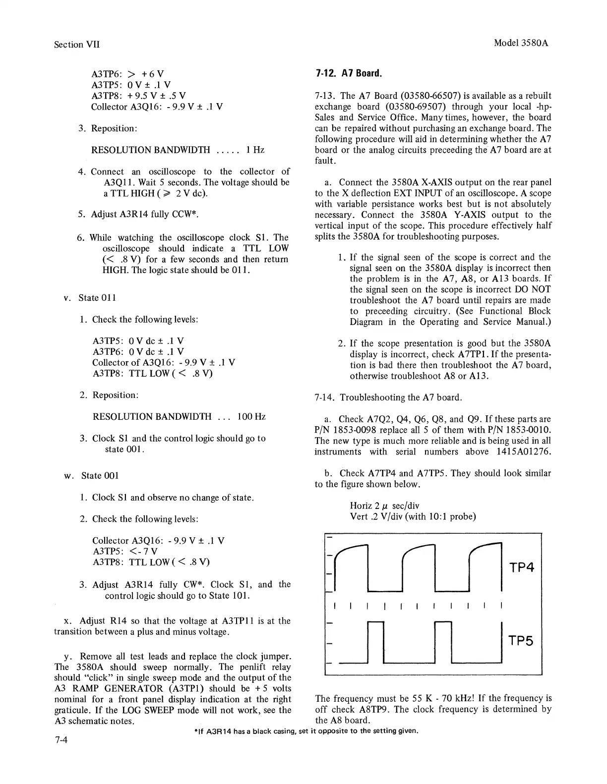
b. Check A 7TP4 and A 7TP5. They should look similar
to
the figure shown below.
Horiz 2 µ sec/div
Vert
.2
V/div (with 10:1 probe)
TP4
TP5
The frequency must be 55 K - 70 kHz!
If
the frequency
is
off
check A8TP9. The clock frequency
is
determined
by
the A8 board.
*If
A3R14
has a
black
casing,
set
it
opposite
to
the
setting given.
7-4