Model 3580A
PERFORMANCE
TESTS
Section V
5-12. Display Accuracy Tests.
a. Reposition the f9llowing front panel controls.
FREQUENCY
.................
00.0 kHz
RESOLUTION BANDWIDTH . . . . . .
300
Hz
FREQ. SPAN/DIV
................
5 KHz
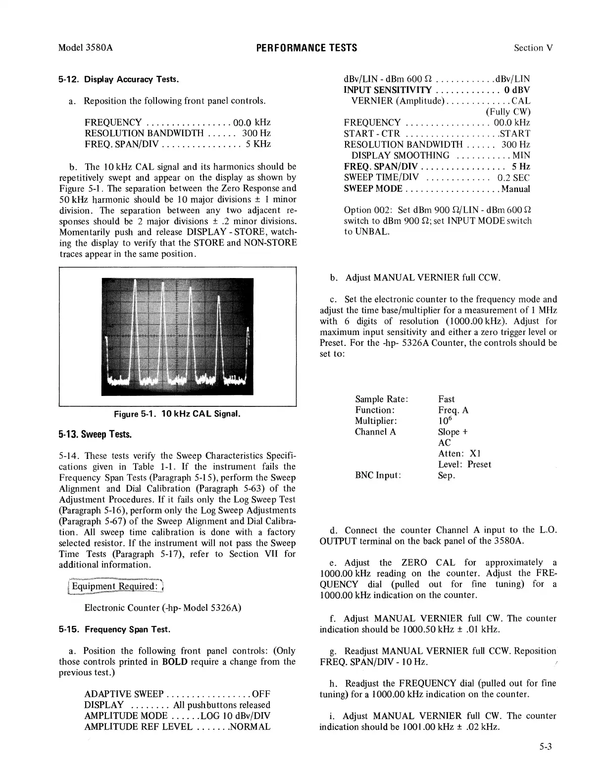
b.
The 10 kHz CAL signal and its harmonics should be
repetitively swept and appear on the display
as
shown by
Figure 5-1. The separation between the Zero Response and
50 kHz harmonic should be 10 major divisions ± 1 minor
division. The separation between any two adjacent re-
sponses should
be
2 major divisions ± .2 minor divisions.
Momentarily push and release DISPLAY - STORE, watch-
ing the display to verify that the STORE and NON-STORE
traces appear in the same position.
Figure 5-1.
10
kHz CAL Signal.
5-13.
Sweep
Tests.
5-14. These tests verify the Sweep Characteristics Specifi-
cations given in Table 1-1.
If
the instrument fails the
Frequency Span Tests (Paragraph 5-15), perform the Sweep
Alignment and
Dial
Calibration (Paragraph 5-63)
of
the
Adjustment Procedures.
If
it fails only the Log Sweep Test
(Paragraph 5-16), perform only the Log Sweep Adjustments
(Paragraph 5-67)
of
the Sweep Alignment and Dial Calibra-
tion. All sweep time calibration
is
done with a factory
selected resistor.
If
the instrument will
not
pass the Sweep
Time Tests (Paragraph 5-17), refer to Section VII for
additional information.
{Ecl~ipment
Reguir;l:'l
Electronic Counter (-hp- Model 5326A)
5-15. Frequency Span Test.
a. Position the following front panel controls: (Only
those controls printed in BOLD require a change from the
previous test.)
ADAPTIVE
SWEEP
.................
OFF
DISPLAY
........
All pushbuttons released
AMPLITUDE MODE
......
LOG 10 dBv/DIV
AMPLITUDE REF LEVEL
.......
NORMAL
dBv/LIN - dBm 600 n
............
dBv/LIN
INPUT SENSITIVITY . . . . . . . . . . . . . 0 dBV
VERNIER (Amplitude)
.............
CAL
(Fully
CW)
FREQUENCY
.................
00.0 kHz
START-CTR
...................
START
RESOLUTION BANDWIDTH . . . . . . 300
Hz
DISPLAY SMOOTHING
...........
MIN
FREQ.
SPAN/DIV...
. . . . . . . . . . . . . . 5
Hz
SWEEP
TIME/DIV . . . . . . . . . . . . . 0.2
SEC
SWEEP
MODE
...................
Manual
Option 002: Set dBm 900 Q/LIN - dBm 600 n
switch to dBm 900 n; set INPUT MODE switch
to
UNBAL.
b. Adjust MANUAL VERNIER full
CCW.
c. Set the electronic counter
to
the frequency mode and
adjust the time base/multiplier for a measurement
of
1
MHz
with 6 digits
of
resolution (1000.00 kHz). Adjust for
maximum input sensitivity and either a zero trigger level or
Preset. For the -hp- 5326A Counter, the controls should be
set to:
Sample Rate:
Function:
Multiplier:
Channel A
BNC
Input:
Fast
Freq. A
106
Slope+
AC
Atten: XI
Level: Preset
Sep.
d. Connect the counter Channel A input
to
the L.O.
OUTPUT terminal
on
the back panel
of
the 3580A.
e. Adjust the ZERO CAL for approximately a
1000.00 kHz reading
on
the counter. Adjust the FRE-
QUENCY dial (pulled
out
for fine tuning) for a
I 000.00 kHz indication on the counter.
f. Adjust MANUAL VERNIER full
CW.
The counter
indication should be I 000.50 kHz ±
.01
kHz.
g.
Readjust MANUAL VERNIER
full
CCW.
Reposition
FREQ. SPAN/DIV
-10
Hz.
h.
Readjust the FREQUENCY dial (pulled
out
for fine
tuning) for a 1000.00 kHz indication
on
the counter.
i.
Adjust MANUAL VERNIER full
CW.
The counter
indication should be 1001.00 kHz ± .02 kHz.
5-3