Section
IV
attenuation. The Input Amplifier provides a fixed
gain
of
approximately 40
dB.
The Output Attenuator, also con-
trolled by the AMPLITUDE REF LEVEL switch provides
- 40
dB,
- 30
dB,
- 20
dB
or - 10
dB
of
signal
attenuation.
Table
4-1
lists the input attenuation, Input Amplifier gain,
output attenuation and the resulting
gain
or attenuation for
each AMPLITUDE REF LEVEL setting. Note that
as
the
AMPLITUDE REF LEVEL switch
is
rotated from the
Xl
(NORMAL) position, the attenuation
is
decreased and the
signal
level
is
increased in steps
of
10
dB.
4-55. The Output Amplifier stage provides the variable
gain
needed to maintain a 0 V rms to 1.2 V rms full-scale output
on all input ranges and reference settings. The
gain
of
the
Output Amplifier
is
controlled by both the INPUT SENSI-
TIVITY switch and the
AMPLITUDE
REF LEVEL switch.
By
observing these two front panel controls, it can
be
noted
that the full-scale reference on the INPUT SENSITIVITY
switch
dial
is
indicated
by
a white window that
is
mechanically linked to the
AMPLITUDE
REF LEVEL
switch. Changing the position
of
either switch changes the
full-scale reference in a 20 V, 10
V,
2
V,
1 V sequence.
This
sequence differs from the 10 dB/step sequence provided by
the
A9
Input Circuit and the attenuators in the Linear
Amplifier. For this reason, the
gain
of
the Output Amplifier
is
changed on alternate ranges.
With
the full-scale reference
set to 10 V, 1 V,
0.1
V, etc., the
gain
of
the Output
Amplifier
is
X56. With the reference set to 20
V,
2 V,
0.2
V,
etc. the
gain
is
increased to X88.
Model 3580A
Table
4-1.
Linear
Amplifier Gain.
Am pl
Input
Ref
Input
Amp
Output
Net Gain
or
Level
Atten.
Gain
Atten.
Atten.
X1
-40dB
+40dB
-40dB
-
40dB
-40dB
+40dB
-30dB
-
30dB
X0.1
-40dB
+40dB
-20
dB
-
20dB
-40dB
+40dB
-10
dB
-
10
dB
X0.01
OdB
+40dB
-40dB
OdB
OdB
+40dB
-30dB
+
10dB
X0.001
OdB
+40dB
-20dB
+
20dB
OdB
+40dB
-10dB
+
30dB
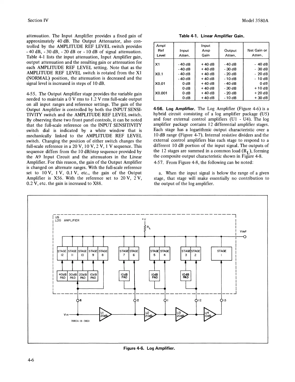
4-56.
Log
Amplifier.
The
Log
Amplifier (Figure 4-6)
is
a
hybrid circuit consisting
of
a log amplifier package (US)
and four external control amplifiers (Ul - U4). The log
amplifier package contains 12 differential amplifier stages.
Each stage has a logarithmic output characteristic over a
10
dB
range (Figure
4-
7). Internal resistive dividers and the
external control amplifiers bias each stage to respond to a
different 10
dB
portion
of
the input signal. The outputs
of
the 12 stages are summed in a common load (RL), forming
the composite output characteristic shown in Figure 4-8.
4-57. From Figure 4-8, the following can
be
noted:
a.
When
the input
signal
is
below the range
of
a
given
stage, that stage
will
make essentially no contribution to
the output
of
the log amplifier.
u5---------------------------------------,
LOG
AMPLIFIER
+V
4-6
40dB 30dB 20dB
IOdB
PAD
PAD
PAD PAD
STAGE
L-----------------------------------------~
6 2 12
13
Vin--------1
3580A-B-3601
Figure
4-6.
Log
Amplifier.
Vout