Model 3580A
and removing the four screws holding the pack
to the side
of
the instrument
chassis.
The
individual battery sticks may short
out
against
the sides
of
the instrument
if
the entire battery
pack
is
not
first removed.
7-32.
To
determine which battery stick
is
faulty, place the
3580A on CHARGE for 14 hours and then run the 3580A
on battery power until the undervoltage relays shut the
battery power off. (Good batteries will run for 5 hours
without a recharge). Measure the voltage across each
battery stick. The nominal voltage should
be
approximately
5 volts per stick. Test for the stick which
is
lower in voltage
than the other battery sticks. A bad stick will differ from
the other battery sticks
by
.5
or more volts.
7-33. The normal warranty period on batteries
is
90 days.
Proper operation implys that the battery, operated under
normal temperatures and load,
will
charge from a state
of
complete discharge in 14 hours, and
will
then power the
instrument for 5 hours
of
continuous and normal use.
7-34.
Cleaning
and
Lubricating
Rotary
Switches.
7-35. Faulty switches can cause intermittent performance,
spurious responses, noise, and many other annoying prob-
lems. Tests
have
shown that the typical operating life
of
a
switch
is
25,000 operations or more. With proper cleaning
and lubrication, this life may be extended to
as
much
as
100,000 or more operations. Freon TF cleaner (-hp- Part
No. 8500-0232)
is
available for cleaning switches. Electro-
tube 2G (-hp- Part No. 5060-6086)
is
available for lubricat-
ing high impedance switches. Electrotube 2A (-hp- Part No.
6040-0300)
is
available for lubricating low impedance
switches. Follow the instructions
given
with these cleaners,
-hp-
Service Note
M45B
(available from your local
-hp-
Sales and Service Office) also
gives
detailed information on
how
to
use
these cleaners.
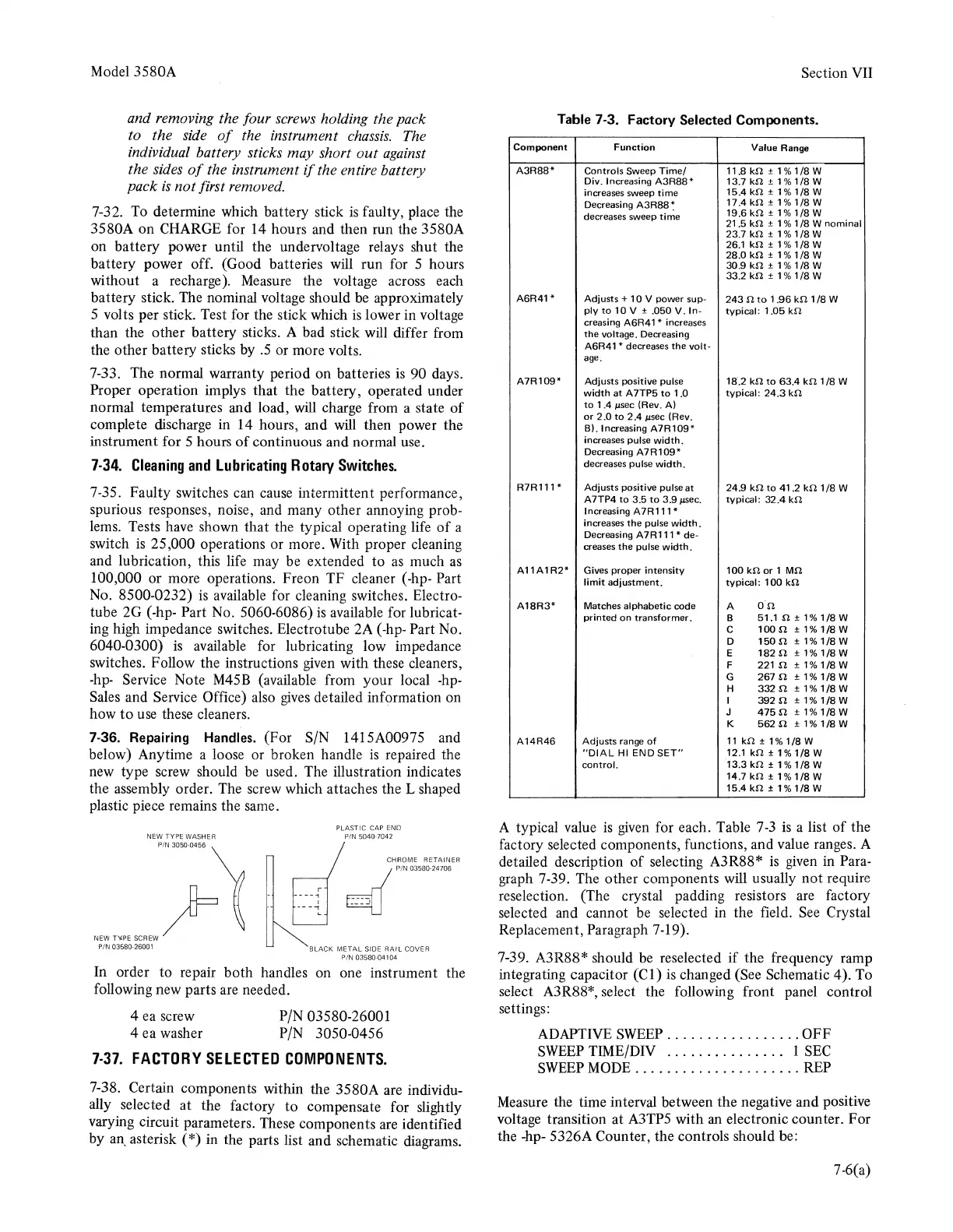
7-36. Repairing Handles. (For S/N 1415A00975 and
below) Anytime a loose or broken handle
is
repaired the
new type screw should
be
used. The illustration indicates
the assembly order. The screw which attaches the L shaped
plastic piece remains the same.
In order to repair both handles on one instrument the
following new parts
are
needed.
4 ea screw P/N 03580-26001
4 ea washer P/N 3050-0456
1·31.
FACTORY
SELECTED
COMPONENTS.
7-38. Certain components within the 3580A are individu-
ally selected
at
the factory
to
compensate for slightly
varying circuit parameters. These components are identified
by
an_
asterisk (*) in the parts list and schematic diagrams.
Section VII
Table
7-3. Factory Selected Components.
Component
Function
Value Range
A3R88*
Controls Sweep
Time/
11.8k.!1±1%1/8W
Div. Increasing
A3R88*
13.7k.!1±1%1/8W
increases sweep time
15.4k.!1±1%1/8W
Decreasing
A3R88:
17.4
k.!1±1%
1/8
w
decreases sweep time
19.6
k.!1±1%
1/8
w
21.5
k.!1±1%1/8
W nominal
23.7
k.!1
± 1%1
/8
w
26.1
k.!1±1%1/8W
28.0
k.!1
± 1 % 1
/8
w
30.9
k.!1±1%
1/8
w
33.2
k.!1
± 1 % 1
/8
w
A6R41*
Adjusts +
10
V power sup-
243
n
to
1 .96
kn
1
/8
W
ply
to
10
V ± .050
V.
In-
typical:
1 .05
k.!1
creasing
A6R41 *
increases
the
voltage. Decreasing
A6R41 *decreases the
volt-
age.
A7R109*
Adjusts positive pulse
18·.2
kn
to
63.4
kn
1
/8
w
width
at
A 7TP5
to
1 .0
typical:
24.3
k.!1
to
1.4
µsec
(Rev.
Al
or
2.0
to
2.4
µsec
(Rev.
BJ. Increasing
A7R109*
increases pulse width.
Decreasing
A7R109*
decreases pulse
width.
R7R111*
Adjusts positive pulse at
24.9
k.!1
to
41.2
k.!11/8 W
A7TP4
to
3.5
to
3.9
µsec.
typical:
32.4
k.!1
Increasing A7R111 *
increases
the
pulse
width.
Decreasing A7R111
*de-
creases
the pulse
width.
A11A1R2*
Gives proper
intensity
100k.!1or1
Mn
limit
adjustment.
typical:
100
k.!1
A18R3*
Matches alphabetic code
A
o·n
printed
on
transformer.
B
51.1.!1±1%1/BW
c
100
n ±
1%
1/8
w
D
1500
±1%1/8W
E
182fl±1%1/8W
F
221n±1%1/8W
G 267 n ±
1%
1/8
w
H
332S'l±1%1/8W
I
392
n ±
1%
1/8
w
J
4750±1%1/8W
K 562 n ±
1%
1/8
w
A14R46
Adjusts range
of
11
k!l±1%1/8W
"DIAL
HI
END
SET"
12.1k.!1±1%
1/8
w
control.
13.3
kn
± 1 % 1
/8
w
14.7
k.!1±1%
1/8
w
15.4
k.!1±1%
1/8
w
A typical value
is
given
for each. Table
7-3
is
a list
of
the
factory selected components, functions, and value ranges. A
detailed description
of
selecting A3R88*
is
given
in Para-
graph 7-39. The other components will usually not require
reselection. (The crystal padding resistors
are
factory
selected and cannot be selected in the field.
See
Crystal
Replacement, Paragraph 7-19).
7-39. A3R88* should
be
reselected
if
the frequency ramp
integrating capacitor
(Cl)
is
changed (See Schematic 4). To
select A3R88*, select the following front panel control
settings:
ADAPTIVE
SWEEP
.................
OFF
SWEEP
TIME/DIV . . . . . . . . . . . . . . . 1
SEC
SWEEP
MODE
.............
,
.......
REP
Measure the time interval between the negative and positive
voltage transition at A3TP5 with an electronic counter. For
the -hp- 5326A Counter, the controls should be:
7-6(a)