Model 3580A
GENERAL
OPERATING
INFORMATION
Section III
Increasing the frequency span or decreasing the sweep time
increases the sweep rate.
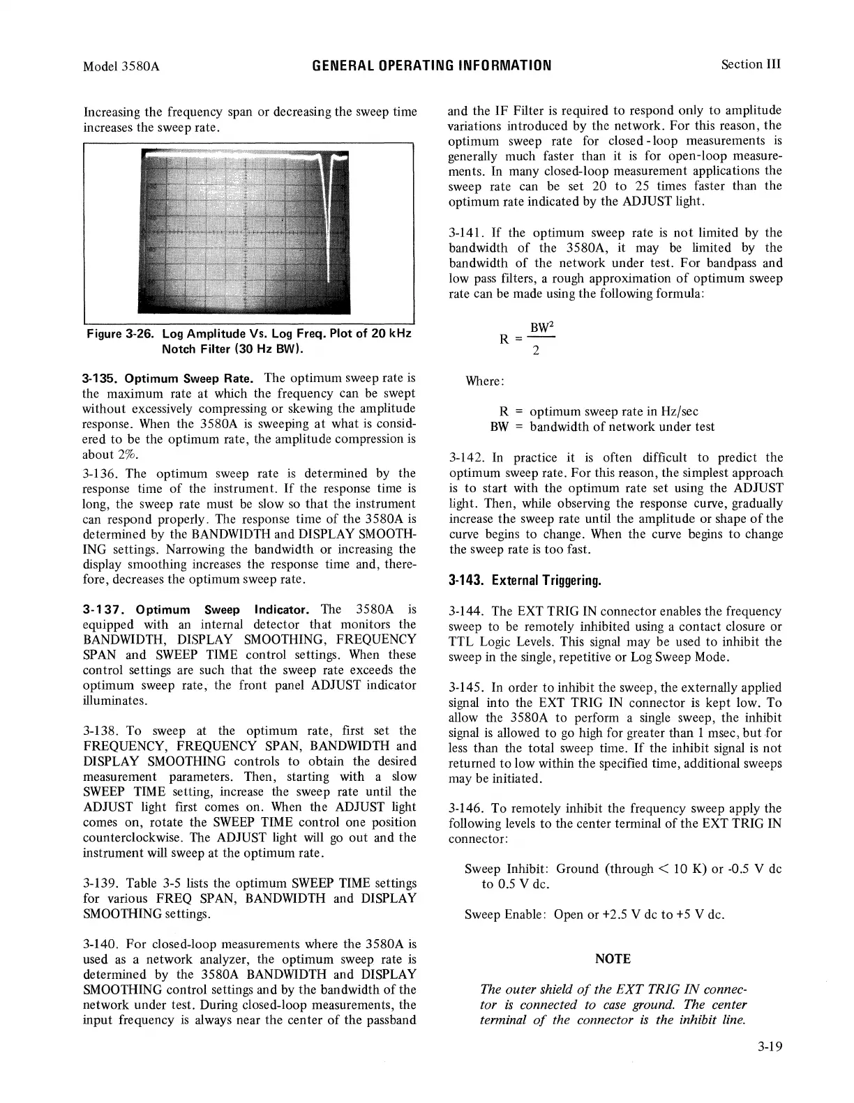
Figure 3-26.
Log
Amplitude Vs.
Log
Freq. Plot of
20
kHz
Notch Filter (30 Hz BW).
3-135. Optimum
Sweep
Rate. The optimum sweep rate
is
the maximum rate at which the frequency can
be
swept
without excessively compressing or skewing the amplitude
response. When the 3580A
is
sweeping
at
what
is
consid-
ered
to
be the optimum rate, the amplitude compression
is
about
2%.
3-136. The optimum sweep rate
is
determined by the
response time
of
the instrument.
If
the response time
is
long, the sweep rate must
be
slow
so
that
the instrument
can respond properly. The response time
of
the 3580A
is
determined by the BANDWIDTH and DISPLAY SMOOTH-
ING settings. Narrowing the bandwidth or increasing the
display smoothing increases the response time and, there-
fore, decreases the optimum sweep rate.
3-137.
Optimum
Sweep
Indicator. The 3580A
is
equipped with
an
internal detector that monitors the
BANDWIDTH, DISPLAY SMOOTHING, FREQUENCY
SPAN and SWEEP TIME control settings. When these
control settings are such that the sweep rate exceeds the
optimum sweep rate, the front panel ADJUST indicator
illuminates.
3-138. To sweep at the optimum rate, first set the
FREQUENCY, FREQUENCY SPAN, BANDWIDTH and
DISPLAY SMOOTHING controls
to
obtain the desired
measurement parameters. Then, starting with a slow
SWEEP
TIME setting, increase the sweep rate until the
ADJUST light first comes on. When the ADJUST light
comes on, rotate the
SWEEP
TIME control one position
counterclockwise. The ADJUST light will
go
out
and the
instrument will sweep at the optimum rate.
3-139. Table 3-5 lists the optimum SWEEP TIME settings
for various FREQ SPAN, BANDWIDTH and DISPLAY
SMOOTHING settings.
3-140.
For
closed-loop measurements where the
3580A
is
used
as
a network analyzer, the optimum sweep rate
is
determined by the 3580A BANDWIDTH and DISPLAY
SMOOTHING control settings and by the bandwidth
of
the
network under test. During closed-loop measurements, the
input frequency
is
always near the center
of
the passband
and the
IF
Filter
is
required to respond only
to
amplitude
variations introduced by the network. For this reason, the
optimum sweep rate for closed -loop measurements
is
generally much faster than it
is
for open-loop measure-
ments. In many closed-loop measurement applications the
sweep rate can be set 20
to
25 times faster than the
optimum rate indicated by the ADJUST light.
3-141.
If
the optimum sweep rate
is
not
limited by the
bandwidth
of
the 3580A, it may
be
limited by the
bandwidth
of
the network under test.
For
bandpass and
low pass filters, a rough approximation
of
optimum sweep
rate can be made using the following formula:
BW
2
R=--
2
Where:
R = optimum sweep rate in Hz/sec
BW
= bandwidth
of
network under test
3-142. In practice it
is
often difficult to predict the
optimum sweep rate.
For
this reason, the simplest approach
is
to
start with the optimum rate set using the ADJUST
light. Then, while observing the response curve, gradually
increase the sweep rate until the amplitude or shape
of
the
curve begins to change. When the curve begins
to
change
the sweep rate
is
too
fast.
3-143.
External
Triggering.
3-144. The EXT TRIG IN connector enables the frequency
sweep to
be
remotely inhibited using a contact closure or
TTL Logic Levels. This signal may be used to inhibit the
sweep in the single, repetitive or Log Sweep Mode.
3-145. In order to inhibit the sweep, the externally applied
signal into the EXT TRIG IN connector
is
kept low. To
allow the 3580A
to
perform a single sweep, the inhibit
signal
is
allowed to
go
high for greater than 1 msec,
but
for
less than the total sweep time.
If
the inhibit signal
is
not
returned
to
low within the specified time, additional sweeps
may be initiated.
3-146. To remotely inhibit the frequency sweep apply the
following levels
to
the center terminal
of
the EXT TRIG IN
connector:
Sweep Inhibit: Ground
(through<
10 K) or -0.5 V de
to
0.5 V de.
Sweep Enable: Open or +2.5 V de
to
+5
V de.
NOTE
The outer shield
of
the
EXT
TRIG
IN
connec-
tor
is
connected to
case
ground. The center
terminal
of
the connector
is
the inhibit
line.
3-19