Model 3580A Section III
SECTION
Ill
OPERATING
INSTRUCTIONS
3-1.
INTRODUCTION.
3-2. This section contains complete operating instructions
for the Model 3580A Spectrum Analyzer. Included
is
a
brief description
of
the instrument, a description
of
controls, general operating information and basic operating
procedures.
J.J.
ABOUT
THE
SPECTRUM
ANALYZER.
3-4. The first spectrum analyzers were introduced during
World
War
II
for use in the development
of
pulse radar
systems. Early spectrum analyzers were difficult to operate
and interpret since they lacked such refinements
as
calibra-
ted controls. They were, however, adequate tools which
enabled scientists
to
observe the spectra
of
radar pulses and
subsequently optimize the gain and bandwidth
of
radar
receivers. Since that time, spectrum analyzers have evolved
into general purpose instruments with unlimited applica-
tions in the
RF
and audio frequency ranges.
3-5. The 3580A
is
a low frequency spectrum analyzer
designed specifically for use in the audio frequency range.
It
can be used
as
a signal analyzer or
as
a network analyzer.
When
used
as
a signal analyzer, the 3580A measures the
amplitudes and frequencies
of
the spectral components
of
an input signal. When used
as
a network analyzer, the
3580A plots the amplitude
vs.
frequency characteristics
of
2-port networks such
as
amplifiers, attenuators and filters.
3-6.
Operating
Features.
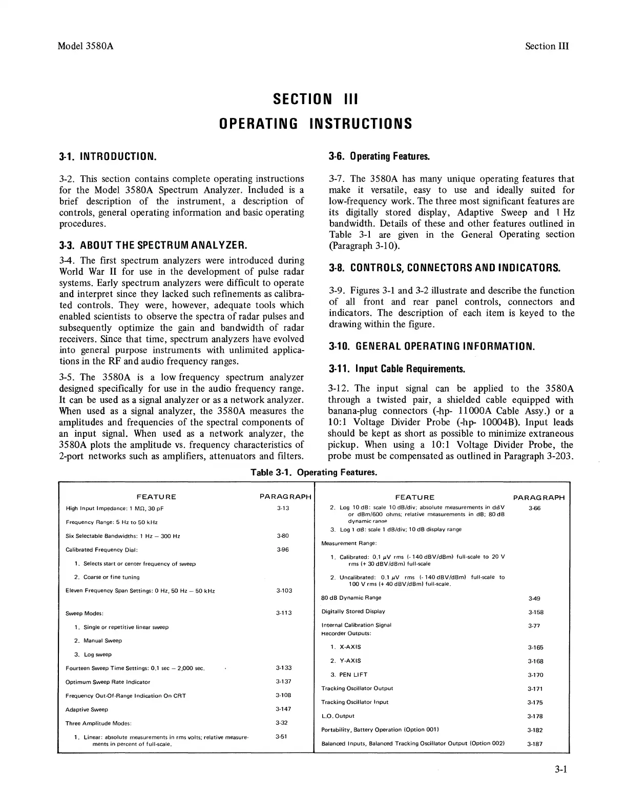
3-7. The 3580A has many unique operating features
that
make it versatile, easy
to
use and ideally suited for
low-frequency work. The three most significant features are
its digitally stored display, Adaptive Sweep and l Hz
bandwidth. Details
of
these and other features outlined in
Table
3-1
are given in the General Operating section
(Paragraph 3-10).
3-8.
CONTROLS,
CONNECTORS
AND
INDICATORS.
3-9. Figures
3-1
and 3-2 illustrate and describe the function
of
all front and rear panel controls, connectors and
indicators. The description
of
each item is keyed
to
the
drawing within the figure.
3-10.
GENERAL
OPERATING
INFORMATION.
3-11.
Input
Cable
Requirements.
3-12. The input signal can be applied
to
the 3580A
through a twisted pair, a shielded cable equipped with
banana-plug connectors (-hp- llOOOA Cable Assy.) or a
10:1 Voltage Divider Probe (-hp- 10004B).
Input
leads
should be kept
as
short
as
possible
to
minimize extraneous
pickup.
When
using a 10: 1 Voltage Divider Probe, the
probe must be compensated
as
outlined in Paragraph 3-203.
Table 3-1. Operating Features.
FEATURE
High
Input
lmp~dance:
1
Mn,
30
pF
Frequency Range: 5
Hz
to
50
kHz
Six Selectable Bandwidths: 1 Hz -
300
Hz
Galibrated Frequency Dial:
1. Selects start or center frequency
of
sweep
2.
Coarse or fine tuning
Eleven Frequency
Span
Settings: 0 Hz,
50
Hz -
50
kHz
Sweep Modes:
1.
Single or repetitive linear sweep
2.
Manual
Sweep
3. Log sweep
Fourteen Sweep Time Settings: 0.1 sec -
2,000
sec.
Optimum Sweep Rate Indicator
Frequency
0111t-Of-Range
Indication On
CRT
Adaptive Sweep
Three Amplitude Modes:
1.
Linear: absolute measurements
in
rms volts; relative measure-
ments in percent
of
full-scale.
PARAGRAPH
3-13
3-80
3-96
3-103
3-113
3-133
3-137
3-108
3-147
3-32
3-51
FEATURE
PARAGRAPH
2.
Log
10
dB:
scale
10 dB/div; absolute measurements in
ddV
3-66
or
dBm/600
ohms; relative measurements in dB;
80
dB
dynamic
ranaf!
3.
Log 1 aB:
scale
1
dB/div;
10
dB
display range
Measurement Range:
1. Calibrated:
0.1
µV
rms
(-140
dBV/d8m)
full-scale
to
20 V
rms
I+
30
dBV
/dBm)
full-scale
2.
Uncalibrated: 0.1
µV
rms I- 140
dBV/dBm)
full-scale
to
100
Vrms
(+40dBV/dBm)
full-scale.
80
dB Dynamic Range
Digitally Stored Display
Internal Calibration Signal
Hecorder Outputs:
1.
X-AXIS
2.
Y-AXIS
3.
PEN
LIFT
Tracking Oscillator
Output
Tracking Oscillator
Input
L.0.
Output
Portability, Battery Operation (Option
001)
Balanced Inputs, Balanced Tracking Oscillator
Output
(Option
002)
3-49
3-158
3-77
3-165
3-168
3-170
3-171
3-175
3-178
3-182
3-187
3-1