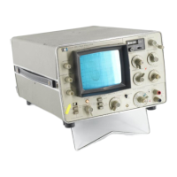
Model 3580A
BASIC
OPERATING
PROCEDURES
Section III
3-194. Battery Operation (Option 001).
a. Connect the low {black) terminal
of
the front panel
INPUT connector
to
earth ground or to
an
appropriate
system ground.
b. Set the POWER switch to the
ON
{BAT) position.
The
POWER
light
will
illuminate.
c. Allow approximately
15
seconds for the CRT to
warm up. Adjust the INTENSITY and FOCUS controls for
a bright, clear presentation on the CRT. When the
instrument
is
initially turned on, the display may
be
similar
to the one shown in Figure 3-34. This display reflects the
preferred states
of
the storage elements in the digital
memory and
is
not
meaningful. To clear the display, press
the CLEAR WRITE button.
d. Allow a warm-up period
of
at least 1 hour before
using the 3580A in a critical measurement application.
e.
To·
recharge the batteries, perform Steps a through d
of
the power-line turn on procedure {Paragraph 3-193 ). Set
the
POWER
switch
to
the CHARGE position. The POWER
light will illuminate. The instrument cannot
be
used while
the batteries are being charged.
The instrument should
not
be
left
in
the
CHARGE mode for prolonged periods. A
charge
period
of
14 hours
is
sufficient to
recharge
a fully discharged battery pack. Ex-
tended periods
of
overcharge
in
ambient tem-
peratures exceeding 30" C ( 86° F) will severely
degrade
battery life and capacity by causing the
cells to overheat.
3-195.
Frequency
Calibration
Procedure.
3-196. The Frequency Calibration Procedure should
be
performed after warm-up each time the instrument
is
turned on.
It
should also
be
performed before and after
using the log sweep.
3-197. For operation in the Repetitive, Single or Manual
sweep mode, proceed
as
follows:
a. Turn the instrument on
as
outlined in Paragraph
3-192.
b. Set the 3580A controls
as
follows:
ADAPTIVE
SWEEP
.................
OFF
DISPLAY
.....
STORE and BLANK STORE
Released
AMPLITUD~MODE
.......
LOG 10 dB/DIV
AMPLITUDE REF LEVEL
.......
NORMAL
dBv/LIN - dBm Switch
...........
dBv/LIN
INPUT SENSITIVITY
...............
CAL
VERNIER
......................
CAL
{Fully
CW)
FREQUENCY
.................
00.0 kHz
START CTR
....................
START
BANDWIDTH
....................
30
Hz
DISPLAY SMOOTHING
.............
MIN
FREQ.
SPAN/DN
..................
N/A
SWEEP
TIME/DIV
.................
N/ A
SWEEP
MODE
...................
RESET
c. ·Clear the display by pressing the CLEAR WRITE
button.
d. Adjust the front panel ZERO
CAL
potentiometer for
peak
zero response. (The zero response will appear
on
the
first line on the left-hand side
of
the display graticule.)
e. Set the BANDWIDTH to 10 Hz. Repeat Step
d.
3-198. For operation in the Log sweep mode, proceed
as
follows:
a.
Set the 3580A controls
as
follows:
ADAPTIVE
SWEEP
.................
OFF
DISPLAY
.....
STORE and BLANK STORE
Released
AMPLITUDE MODE
.......
LOG
10 dB/DIV
AMPLITUDE REF LEVEL
.......
NORMAL
dBv/LIN - dBm Switch
...........
dBv/LIN
INPUT SENSITIVITY
...............
CAL
VERNIER
......................
CAL
{Pully
CW)
FREQUENCY
.....................
N/ A
START CTR
......................
N/A
BANDWIDTH
. . . . . . . . . . . . . . . . . . .
30
Hz
DISPLAY SMOOTHING
.............
MIN
FREQ. SPAN/DIV
..................
N/A
SWEEP
TIME/DIV
.................
N/ A
SWEEP
MODE
...............
LOG ZERO
b. Clear the display by pressing the CLEAR WRITE
button.
c. Adjust the front panel ZERO CAL potentiometer for
peak zero response. (The zero response will appear
on
the
first line on the left-hand side
of
the display graticule.)
3-199.
Amplitude
Calibration
Procedure.
3-200. The Amplitude Calibration Procedure should
be
performed initially after warm-up and each time the
BANDWIDTH
setting
is
changed.
3-201. For operation on the 1
Hz
or 3 Hz BANDWIDTH,
proceed
as
follows:
a.
Tum the instrument on {Paragraph 3-192) and
perform the Frequency Calibration Procedure (Paragraph
3-195).
3-27

 Loading...