Model
3580A
GENERAL
OPERATING
INFORMATION
Section III
~-~1IVERNIERI
INPUT
SENSITIVITY Q
q
__
\
INPUT
CIRCUITS
IOOKHz to 150KHz
FROM
VTO
OVERLOAD
DETECTOR
I BANDWIDTH!
MIXER
Q
I
I
I
IF
FILTER
(IOOKHz)
AMPLITUDE
REF
LEVEL
0
r----------~-----,
I I
'
LINEAR
IF
IF
I
AMPLIFIER ATTENUATOR I
~--~1
L----------------J
VIDEO
DETECTOR
VIDEO OUTPUT
3580-
B-
3593
VIDEO
TO
DISPLAY
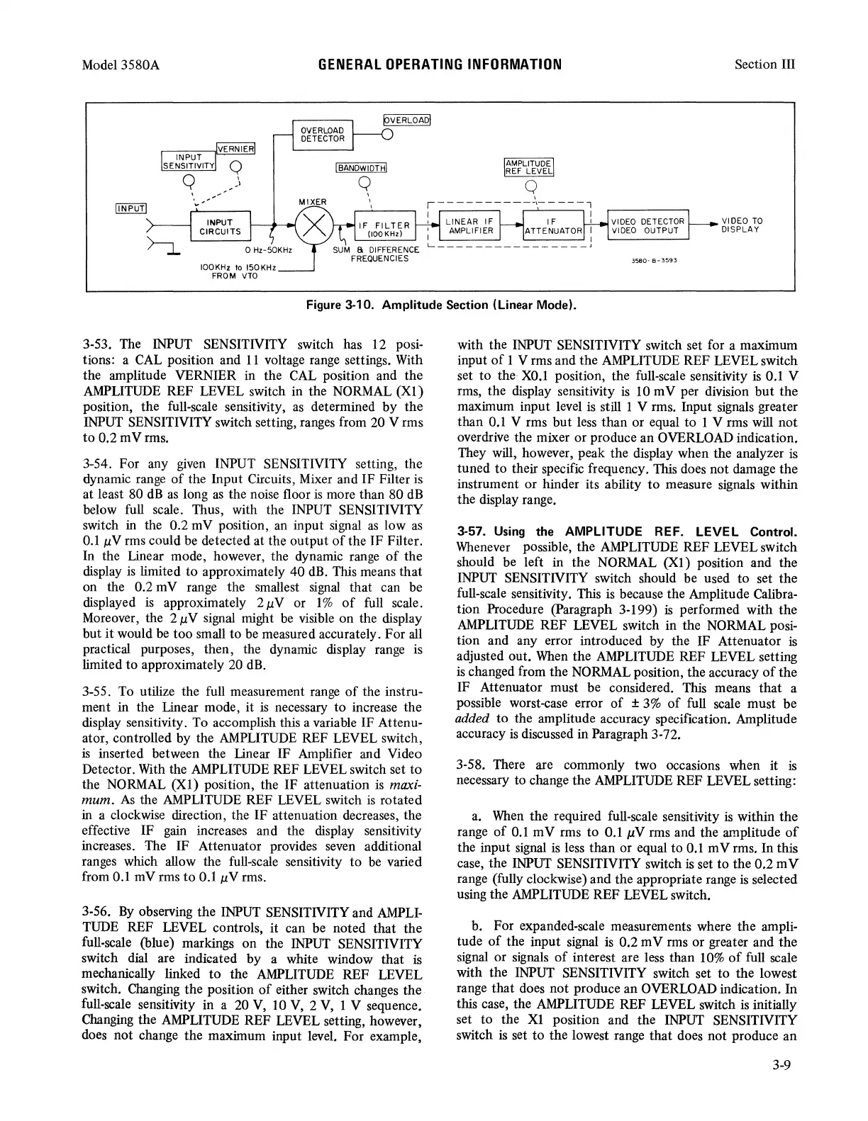
Figure 3-10. Amplitude Section (Linear Mode).
3-53. The
INPUT
SENSITIVITY switch has
12
posi-
tions: a
CAL
position and
11
voltage range settings.
With
the amplitude VERNIER in the
CAL
position and the
AMPLITUDE
REF LEVEL switch in the
NORMAL
(Xl)
position, the full-scale sensitivity,
as
determined by the
INPUT
SENSITIVITY switch setting,
ranges
from 20 V rms
to
0.2 m V
rms.
3-54. For any
given
INPUT SENSITIVITY setting, the
dynamic
range
of
the Input Circuits,
Mixer
and IF Filter
is
at least 80
dB
as
long
as
the noise floor
is
more than 80
dB
below
full
scale. Thus, with the
INPUT
SENSITIVITY
switch
in
the 0.2 mV position,
an
input
signal
as
low
as
0.1
µV
rms could be detected at the output
of
the IF Filter.
In the Linear mode, however, the dynamic
range
of
the
display
is
limited to approximately 40
dB.
This means that
on the 0.2 m V range the smallest
signal
that can be
displayed
is
approximately 2 µ V or 1 %
of
full
scale.
Moreover, the 2 µ V signal might
be
visible on the display
but
it
would
be
too small to
be
measured accurately. For
all
practical purposes, then, the dynamic display range is
limited to approximately 20
dB.
3-55.
To
utilize the
full
measurement
range
of
the instru-
ment in the Linear mode, it
is
necessary to increase the
display sensitivity.
To
accomplish this a variable IF Attenu-
ator, controlled by the
AMPLITUDE
REF LEVEL switch,
is
inserted between the Linear IF Amplifier and Video
Detector.
With
the
AMPLITUDE
REF LEVEL switch set
to
the
NORMAL
(Xl)
position, the IF attenuation
is
maxi-
mum.
As
the
AMPLITUDE
REF LEVEL switch
is
rotated
in
a clockwise direction, the IF attenuation decreases, the
effective IF
gain
increases and the display sensitivity
increases. The IF Attenuator provides
seven
additional
ranges
which allow the full-scale sensitivity
to
be
varied
from
0.1
mV rms
to
0.1
µV
rms.
3-56.
By
observing the
INPUT
SENSITIVITY and
AMPLI-
TUDE
REF LEVEL controls, it can be noted that the
full-scale (blue) markings on the
INPUT
SENSITIVITY
switch dial are indfoated by a white window that
is
mechanically linked
to
the
AMPLITUDE
REF LEVEL
switch. Changing the position
of
either switch changes the
full-scale sensitivity in a 20
V,
10
V,
2
V,
1 V sequence.
Changing
the
AMPLITUDE
REF LEVEL setting, however,
does
not change the maximum input level. For example,
with the
INPUT
SENSITIVITY switch set for a maximum
input
of
1 V rms and the
AMPLITUDE
REF LEVEL switch
set to the
X0.1
position, the full-scale sensitivity
is
0.1
V
rms, the display sensitivity
is
10
m V per division
but
the
maximum input level
is
still 1 V rms. Input signals greater
than
0.1
V rms but
less
than or equal to 1 V rms will not
overdrive the mixer or produce an OVERLOAD indication.
They will, however, peak the display when the analyzer is
tuned to their specific frequency. This does not damage the
instrument or hinder its ability to measure signals within
the display range.
3-57. Using the
AMPLITUDE
REF.
LEVEL
Control.
Whenever
possible, the
AMPLITUDE
REF LEVEL switch
should be left in the
NORMAL
(Xl)
position and the
INPUT
SENSITIVITY switch should be used to set the
full-scale sensitivity. This
is
because the Amplitude Calibra-
tion Procedure (Paragraph 3-199)
is
performed with the
AMPLITUDE
REF LEVEL switch in the
NORMAL
posi-
tion and any error introduced by the IF Attenuator is
adjusted out.
When
the
AMPLITUDE
REF LEVEL setting
is
changed from the
NORMAL
position, the accuracy
of
the
IF Attenuator must be considered.
This
means that a
possible worst-case error
of
±
3%
of
full
scale must be
added to the amplitude accuracy specification. Amplitude
accuracy
is
discussed in Paragraph 3-72.
3-58. There are commonly two occasions when it
is
necessary to change the
AMPLITUDE
REF LEVEL setting:
a.
When
the required full-scale sensitivity is within the
range
of
0.1
mV rms to 0.1
µV
rms and the amplitude
of
the input
signal
is
less than or equal to
0.1
m V rms. In this
case, the
INPUT
SENSITIVITY switch
is
set to the 0.2 m V
range (fully clockwise) and the appropriate range is selected
using the
AMPLITUDE
REF LEVEL switch.
b. For expanded-scale measurements where the ampli·
tude
of
the input
signal
is 0.2 m V rms or greater and the
signal
or
signals
of
interest are
less
than
10%
of
full scale
with the
INPUT
SENSITIVITY switch set to the lowest
range that does not produce an OVERLOAD indication.
In
this case, the
AMPLITUDE
REF LEVEL switch is initially
set to the
Xl
position and the
INPUT
SENSITIVITY
switch is set to the lowest range that does not produce an
3-9