Section III
BASIC
OPERATING
PROCEDURES
Model 3580A
3-191.
BASIC
OPERATING
PROCEDURES.
3-192.
Instrument
Tum
On.
3-193. Power Line Operation.
a.
Check the line voltage at the point
of
installation.
b. Refer to Figure 3-33 and set the 3580A for the line
voltage to
be
used (100
V,
120
V,
220 V or 240 V).
line
voltage must
be
within +
5%
to
-
10%
of
voltage setting.
c.
Verify that the proper
fuse
is
installed in the fuse
holder:
line
Setting Fuse Type -hp- Part No.
lOOV/120 V
0.5
A,
250 V 2110-0012
Normal
Blow
220V/240
V
0.25
A,
250 V 2110-0004
Normal
Blow
d. Connect the detachable
ac
power cord to the rear
panel power receptacle and
to
the power source.
e.
Set the POWER switch
to
the
ON
(AC) position. The
POWER
light
will
illuminate.
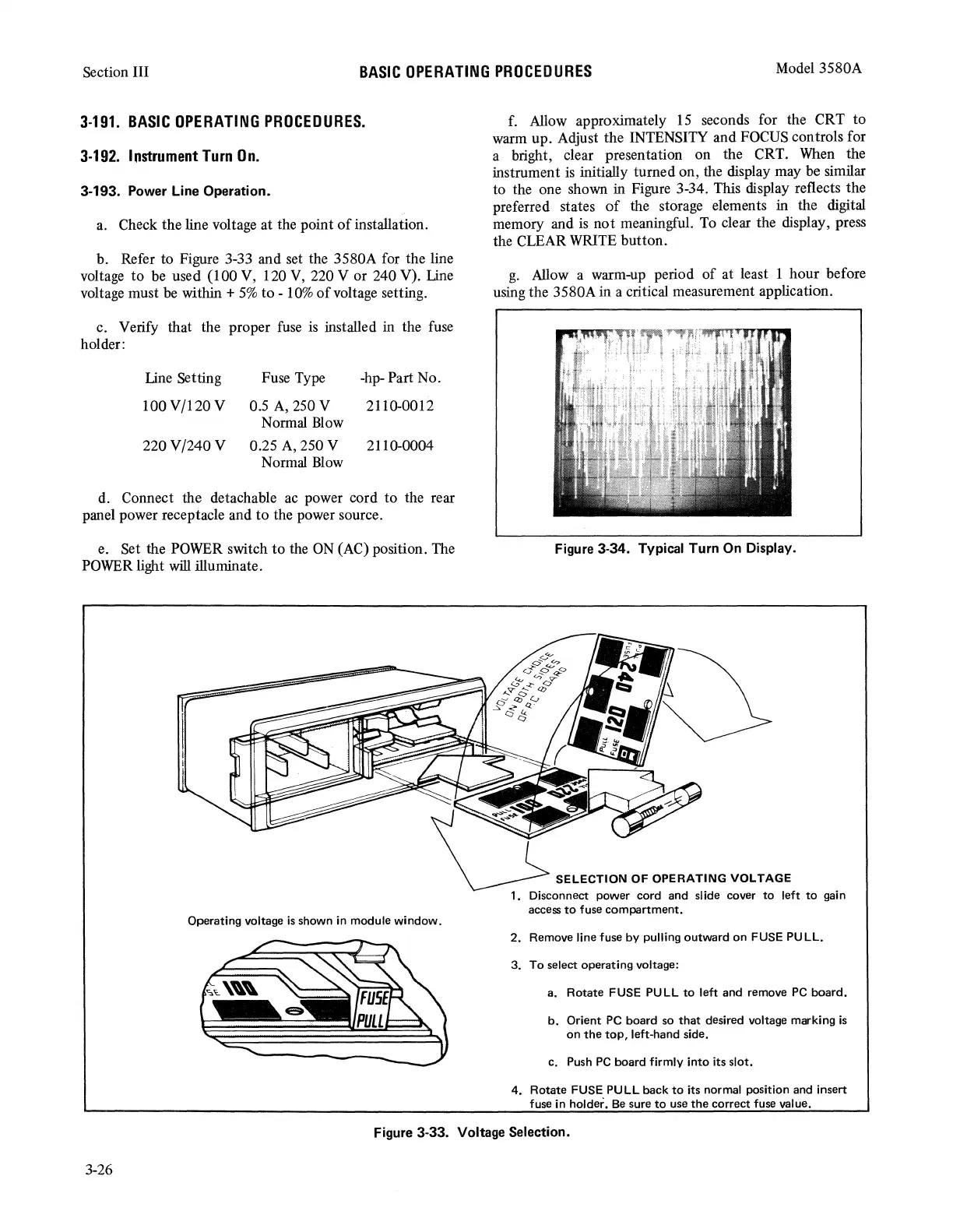
Operating voltage
is
shown in module
window.
f.
Allow approximately
15
seconds for the CRT to
warm up. Adjust the INTENSITY and
FOCUS
controls for
a bright, clear presentation on the CRT.
When
the
instrument
is
initially turned on, the display may be similar
to the one shown in Figure 3-34. This display reflects the
preferred states
of
the storage elements in the digital
memory and is not meaningful.
To
clear the display, press
the CLEAR
WRITE
button.
g.
Allow a warm-up period of at least 1 hour before
using the 3580A in a critical measurement application.
Figure 3-34. Typical
Turn
On Display.
SELECTION
OF
OPERATING VOLTAGE
1. Disconnect power cord and slide cover
to
left
to
gain
access
to
fuse
compartment.
2.
Remove line fuse by pulling
outward
on
FUSE PULL.
3.
To
select operating voltage:
a.
Rotate
FUSE PULL
to
left and remove
PC
board.
b.
Orient PC
board
so
that
desired voltage marking
is
on
the
top,
left-hand side.
c. Push
PC
board
firmly
into
its slot.
4.
Rotate
FUSE PULL back
to
its normal position and insert
fuse in holder.
Be
sure
to
use
the
correct
fuse value.
Figure 3-33. Voltage Selection.
3-26