Section III
GENERAL
OPERATING
INFORMATION
Model 3580A
3-175.
Tracking
0
scillator
Input.
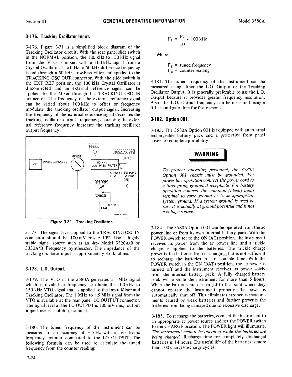
3-176. Figure
3-31
is
a simplified block diagram
of
the
Tracking Oscillator circuit. With the rear panel slide switch
in
the NORMAL position, the 100 kHz to 150 kHz signal
from the VTO
is
mixed with a 100 kHz signal from a
Crystal Oscillator. The 0
Hz
to 50 kHz difference frequency
is
fed through a 50 kHz Low-Pass Filter and applied
to
the
TRACKING
OSC
OUT connector. With the slide switch in
the EXT REF position, the 100 kHz Crystal Oscillator
is
disconnected and an external reference signal can
be
applied to the Mixer through the TRACKING
OSC
IN
connector. The frequency
of
the external reference signal
can
be
varied about 100 kHz to offset
or
frequency
modulate the tracking oscillator
output
signal. Increasing
the frequency
of
the external reference signal decreases the
tracking oscillator
output
frequency; decreasing the exter-
nal reference frequency increases the tracking oscillator
output
frequency.
q
'
50
KHz
LOW
PASS
Fl L TER
iNoRMA[:
L.
_____
J
O
Hz
to
50
KHz
O
V-
2 v rms
100 KHz
XTAL.
DSC.
3580-
B •
3595
Figure 3-31. Tracking Oscillator.
3-177. The signal level applied to the TRACKING
OSC
IN
connector should be 100 mV rms ± 10%. Use a highly
stable signal source such
as
an
-hp- Model 3320A/B or
3330A/B Frequency Synthesizer. The impedance
of
the
tracking oscillator input
is
approximately 3.6 kilohms.
3-178.
LO.
Output.
3-179. The VTO
in
the
3580A
generates a 1
MHz
signal
which
is
divided
in
frequency to obtain the 100 kHz to
150 kHz VTO signal that
is
applied to the Input Mixer and
Tracking Oscillator. The 1
MHz
to 1.5
MHz
signal from the
VTO
is
available
at
the rear panel
LO
OUTPUT connector.
The signal level at the
LO
OUTPUT
is
100 mV rms;
output
impedance
is
1 kilohm, nominal.
3-180. The tuned frequency
of
the instrument can be
measured
to
an accuracy
of
± 5
Hz
with an electronic
frequency counter connected to the
LO
OUTPUT. The
following formula can be used to calculate the tuned
frequency from the counter reading:
3-24
Ft
= Fe - l 00 kHz
10
Where:
Ft
tuned frequency
F c = counter reading
3-181. The
tuned
frequency
of
the instrument can be
measured using either the L.O.
Output
or
the Tracking
Oscillator Output.
It
is
generally preferable
to
use the L.O.
Output
because it provides greater frequency resolution.
Also, the
L.0.
Output frequency can be measured using a
0.1 second gate time for fast response.
3-182.
0
ption
001.
3-183. The 3580A Option 001
is
equipped with an internal
rechargeable battery pack and a protective front panel
cover for complete portability.
I
WARNING
I
To protect operating personnel, the 3580A
Option
001
chassis must be grounded. For
power line operation connect the power cord to
a three-prong grounded receptacle. For battery
operation connect the common (black) input
terminal to earth ground or to
an
appropriate
system ground.
If
a system ground
is
used
be
sure
it
is
actually at ground potential and
is
not
a voltage source.
3-184. The 3580A Option 001 can be operated from the
ac
power line
or
from its own internal battery pack. With the
POWER switch set to the
ON
(AC) position, the instrument
receives its power from the ac power line and a trickle
charge
is
applied to the batteries. The trickle charge
prevents the batteries from discharging,
but
is
not sufficient
to recharge the batteries in a reasonable time. With the
POWER switch in the
ON
(BAT) position, the ac power
is
turned
off
and the instrument receives its power solely
from the internal battery pack. A fully charged battery
pack will operate the instrument for more than 5 hours.
When the batteries are discharged
to
the point where they
cannot operate the instrument properly, the power
is
automatically shut off. This eliminates erroneous measure-
ments caused by weak batteries and further prevents the
batteries from being damaged due
to
excessive discharge.
3-185. To recharge the batteries, connect the instrument
to
an
appropriate ac power source and set the POWER switch
to the CHARGE position. The POWER light will illuminate.
The instrument cannot
be
operated while the batteries
are
being
charged.
Recharge time for completely discharged
batteries
is
14 hours. The useful life
of
the batteries
is
more
than 100 charge/discharge cycles.