Model 3S80A
ADJUSTMENT
PROCEDURES
Section V
c. Fine tune the FREQUENCY dial for a maximum
display indication.
d.
Reposition the following front panel controls:
RESOLUTION BANDWIDTH . . . . . .
300
Hz
SWEEP
MODE
.....................
REP
e. Adjust ASC14 (STAGE S CRYSTAL BALANCE
ADJ.) for equal and symmetrical skirts on the right and left
halves
of
the CRT display.
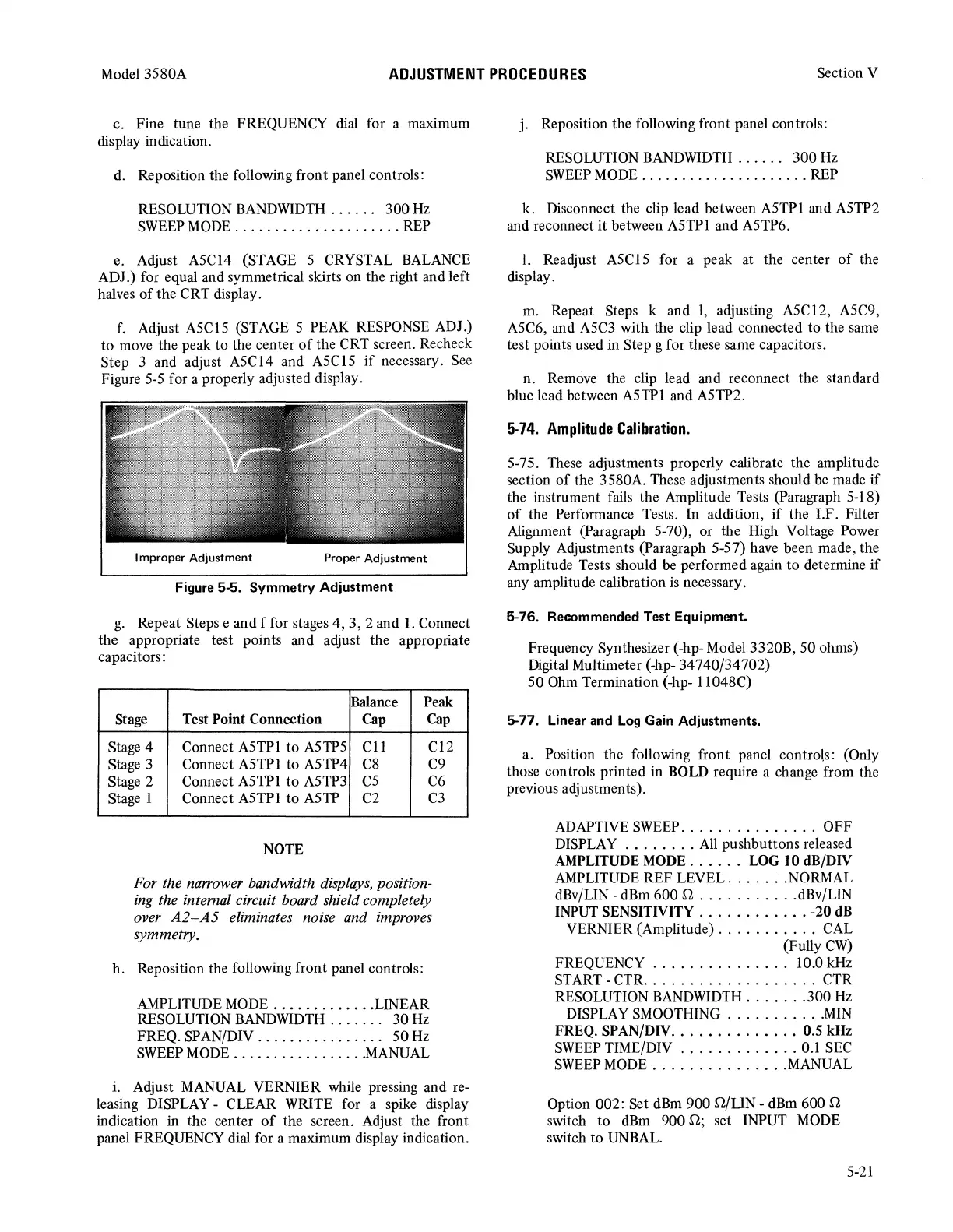
f.
Adjust ASClS (STAGE S PEAK RESPONSE ADJ.)
to
move the peak to the center
of
the CRT screen. Recheck
Step 3 and adjust ASC14 and ASClS
if
necessary.
See
Figure
S-S
for a properly adjusted display.
Figure 5-5.
Symmetry
Adjustment
g.
Repeat Steps e and f for stages
4,
3,
2 and
1.
Connect
the appropriate test points and adjust the appropriate
capacitors:
Balance Peak
Stage
Test Point Connection Cap Cap
Stage 4
Connect ASTPl
to
ASTPS
Cl
1 C12
Stage 3
Connect ASTPl
to
ASTP4
C8
C9
Stage 2
Connect ASTPl
to
ASTP3
cs
C6
Stage 1 Connect ASTPl
to
ASTP
C2
C3
NOTE
For the na"ower bandwidth displays, position-
ing the internal circuit board shield completely
over
A2-A5
eliminates noise and improves
symmetry.
h.
Reposition the following front panel controls:
AMPLITUDE
MODE
.............
LINEAR
RESOLUTION BANDWIDTH . . . . . . .
30
Hz
FREQ. SPAN/DIV . . . . . . . . . . . . . . . .
SO
Hz
SWEEP
MODE
................
MANUAL
i. Adjust MANUAL VERNIER while pressing and re-
leasing DISPLAY - CLEAR WRITE for a spike display
indication in the center
of
the screen. Adjust the front
panel FREQUENCY dial for a maximum display indication.
j. Reposition the following front panel controls:
RESOLUTION BANDWIDTH . . . . . . 300 Hz
SWEEP
MODE
.....................
REP
k. Disconnect the clip lead between ASTPl and ASTP2
and reconnect
it
between ASTPl and ASTP6.
I. Readjust ASCl S for a peak at the center
of
the
display.
m. Repeat Steps k and
1,
adjusting ASC12, ASC9,
ASC6, and
ASC3
with the clip lead connected to the same
test points used in Step g for these same capacitors.
n. Remove the clip lead and reconnect the standard
blue lead between ASTPl and ASTP2.
5-74.
Amplitude
Calibration.
S-7S. These adjustments properly calibrate the amplitude
section
of
the 3S80A. These adjustments should be made
if
the instrument fails the Amplitude Tests (Paragraph S-18)
of
the Performance Tests. In addition,
if
the I.F. Filter
Alignment (Paragraph S-70), or the High Voltage Power
Supply Adjustments (Paragraph S-S7) have been made, the
Amplitude Tests should be performed again
to
determine
if
any amplitude calibration
is
necessary.
5-76. Recommended Test Equipment.
Frequency Synthesizer (-hp- Model 3320B,
SO
ohms)
Digital Multimeter (-hp- 34740/34702)
SO
Ohm Termination (-hp- 11048C)
5-77. Linear and Log Gain Adjustments.
a. Position the following front panel controls: (Only
those controls printed in BOLD require a change from the
previous adjustments).
ADAPTIVE
SWEEP
...............
OFF
DISPLAY
........
All
pushbuttons released
AMPLITUDE
MODE
. . . . . . LOG 10
dB/DN
AMPLITUDE REF LEVEL
.....
; .NORMAL
dBv/LIN -dBm 600 Q
...........
dBv/LIN
INPUT SENSITNITY
............
-20
dB
VERNIER (Amplitude)
...........
CAL
(Fully
CW)
FREQUENCY . . . . . . . . . . . . . . . 10.0 kHz
START-CTR
...................
CTR
RESOLUTION BANDWIDTH
.......
300
Hz
DISPLAY SMOOTHING
...........
MIN
FREQ.
SPAN/DN
..............
0.5 kHz
SWEEP
TIME/DIV
.............
0.1
SEC
SWEEP
MODE
...............
MANUAL
Option 002: Set dBm 900 Q/LIN - dBm 600 Q
switch
to
dBm
900 Q; set INPUT MODE
switch
to
UNBAL.
S-21