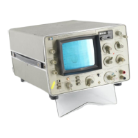
Model 3580A
Section IV
SECTION
IV
THEORY
OF
OPERATION
4-1.
INTRODUCTION.
4-2. This section contains a Simplified Block Diagram
Description and a Functional Description
of
the 3580A
Spectrum Analyzer.
4-3.
SIMPLIFIED
BLOCK
DIAGRAM
DESCRIPTION.
4-4. Refer to the Simplified Block Diagram (Figure 4-1) for
the following discussion.
The 3580A can
be
divided into four major sections:
1) Amplitude Section
2) Frequency and Sweep Section
3) Digital Storage Section
4) Display
4-5.
Amplitude
Section.
4-6. The Amplitude Section consists
of
an Input Circuit,
an
Overload Detector, an Input Mixer,
an
IF Filter,
Log
and
Linear IF Amplifiers, a Video Detector, a Video Filter and
a Video Output Circuit.
4-7. Input Circuits. The Input Circuits, controlled by the
front panel INPUT SENSITIVITY switch, provide the gain
or
attenuation needed
to
maintain the proper signal
level
at
the input
of
the Mixer. The Input Circuits also contain a
50 kHz low-pass filter which prevents image frequencies
(200 kHz and above) from reaching the Mixer.
4-8. Overload Detector. The Overload Detector at the
input
of
the Mixer senses when the input level exceeds the
design limits and, in turn, lights the front panel OVER-
LOAD indicator. This
is
an important function since signals
that overdrive the mixer can produce harmonic and
spurious mixing products which ultimately appear on the
display.
4-9. Input Mixer. The Input Mixer
is
a double-balanced
active mixer in which the 0
Hz
to 50 kHz input signal
is
mixed with a 100 kHz to 150 kHz signal from the
Voltage-Tuned Local Oscillator (VTO). The
output
of
the
Mixer is a composite signal containing the upper and lower
sidebands.
4-10. To select a given frequency component present at the
input
of
the Mixer, the VTO frequency
is
tuned
so
that
the
difference between
it
and the frequency
of
interest
is
100 kHz:
Fvto - Fin = 100 kHz
Where:
Fvto = 100 kHz to 150 kHz VTO frequency
Fin=
0
Hz
to 50 kHz input frequency
The
100 kHz intermediate frequency (IF)
is
fed through
the IF Filter, detected and displayed on the CRT. Signals
outside the passband
of
the IF Filter are rejected.
4-11.
IF
Filter. The IF Filter contains
five
cascaded crystal
filter stages. The center frequency
of
the filter
is
100 kHz
and the 3
dB
bandwidth varies from 1
Hz
to
300 Hz
as
a
function of the front panel
BANDWIDTH
setting. Since the
Input Circuits and Input Mixer are broadband through
50 kHz, the selectivity
of
the instrument
is
determined
entirely by the bandwidth
of
the IF Filter.
4-12.
Log
and
Linear Amplifiers. The 100 kHz output
of
the IF Filter
is
applied to the Video Detector through a Log
Amplifier
in
the
Log
amplitude mode or through a Linear
Amplifier
in
the Linear amplitude mode. The Log Amplifier
converts the amplitude
of
the incoming
IF
signal to a
logarithmic value, providing
an
80
dB
display range. The
linear
Amplifier
is
a conventional amplifier circuit in which
the gain
is
varied to provide the 20 V,
10
V, 2 V, 1 V
ranging sequence used in the
linear
mode. Also, the Linear
Amplifier contains a variable attenuator which increases the
overall gain.
as
the AMPLITUDE REF LEVEL switch
is
changed from the XI position.
4-13. Video Detector. The Video Detector
is
an average-
responding, full-wave detector circuit which produces a de
voltage proportional
to
the amplitude
of
the 100 kHz log or
linear input signal.
4-14. Video Filter. The Video Filter
is
an R/C filter
network controlled by the BANDWIDTH and DISPLAY
SMOOTHING controls. The purpose
of
the filter
is
to
smooth-out the ripple and noise riding on the detected
video signal.
4-15. Video Output Circuit. The Video Output Circuit
functions
as
an
output
buffer in the Linear mode and
as
a
variable
gain
amplifier in the
Log
10
dB
and Log 1
dB
modes. In the
Log
10
dB
mode, a variable
de
offset voltage,
controlled by the AMPLITUDE REF LEVEL switch,
is
summed with the video input signal. This allows the entire
display
to
be offset in steps
of
10
dB
as
the AMPLITUDE
REF LEVELsetting
is
changed from 0
dB
to
- 70 dB. In the
Log 1
dB
mode, the gain
of
the Video Output Circuit
is
increased to provide an expanded scale
of
1 dB per division.
Changing the AMPLITUDE REF LEVEL setting then varies
4-1

 Loading...