Section III
BASIC
OPERATING
PROCEDURES
Model 3580A
b. Set the 3580A controls
as
follows:
DISPLAY
.....
STORE and BLANK S'fORE
Released
AMPLITUDE MODE
.......
LOG 10 dB/DIV
AMPLITUDE REF LEVEL
.......
NORMAL
dBv
/LIN - dBm Switch
...........
dBv
/LIN
INPUT SENSITIVITY
...............
CAL
VERNIER
.......................
CAL
(Fully
CW)
FREQUENCY . . . . . . . . . . . . . . . . 10.0 kHz
START CTR
......................
CTR
BANDWIDTH . . . . . . . . . . . . . . 1
Hz
or 3 Hz
(whichever
is
to
be used)
DISPLAY SMOOTHING
.............
MIN
FREQ. SPAN/DIV
..................
0 Hz
SWEEP
TIME/DIV
.................
NJ
A
SWEEP
MODE
....................
MAN
c. Turn the ADAPTIVE
SWEEP
control to the
on
position
so
the sweep marker (gap) appears on the
horizontal trace. Leave the baseline threshold at the
bottom
of
the screen.
d.
While
pressing the CLEAR WRITE
button,
adjust the
MANUAL VERNIER so
that
the sweep marker
is
in the
center
of
the display. Release the CLEAR WRITE
button
and set the ADAPTIVE
SWEEP
control
to
the
OFF
position.
e. Pull
out
on the FREQUENCY control for fine
tuning. Carefully adjust the FREQUENCY control for a
peak
10
kHz response in the center
of
the display.
f.
Using a small screwdriver, adjust the front panel CAL
10 KHz potentiometer so
that
the peak
of
the 10 kHz
response
is
exactly full scale.
g.
Set the AMPLITUDE MODE
to
LOG 1 dB/DIV.
Repeat Step
f.
3-202. For operation
on
the 10
Hz,
30
Hz, 100
Hz
or
300
Hz
BANDWIDTH proceed
as
follows:
a. Turn the instrument on (Paragraph 3-192) and
perform the Frequency Calibration Procedure (Paragraph
3-195).
b. Set the 3580A controls
as
follows:
3-28
DISPLAY
.....
STORE and BLANK STORE
Released
AMPLITUDE MODE
.......
LOG 10 dB/DIV
AMPLITUDE REF LEVEL
.......
NORMAL
dBv
/LIN - dBm Switch
...........
dBv
/LIN
INPUT SENSITIVITY
...............
CAL
VERNIER
......................
CAL
(Fully
CW)
FREQUENCY . . . . . . . . . . . . . . . . 10.0 kHz
START CTR
......................
CTR
BANDWIDTH . . . . . . . . . . . . 10
Hz-300
Hz
(whichever
is
to
be used)
DISPLAY SMOOTHING
.............
MIN
FREQ. SPAN/DIV
...........
See
Table 3-6
SWEEP
TIME/DIV
..........
See
Table 3-6
SWEEP
MODE
.....................
REP
c. Using the ADAPTIVE
SWEEP
control, set the base-
line threshold
to
- 60
dB
on the display.
d. Using a small screwdriver, adjust the front panel CAL
10 KHz potentiometer
so
that the peak
of
the 10 kHz
response
is
exactly full scale.
e.
Set the AMPLITUDE' MODE to LOG 1 dB/DIV.
Using the ADAPTIVE
SWEEP
control, set the baseline
threshold
to
the
bottom
of
the display. Repeat Step d.
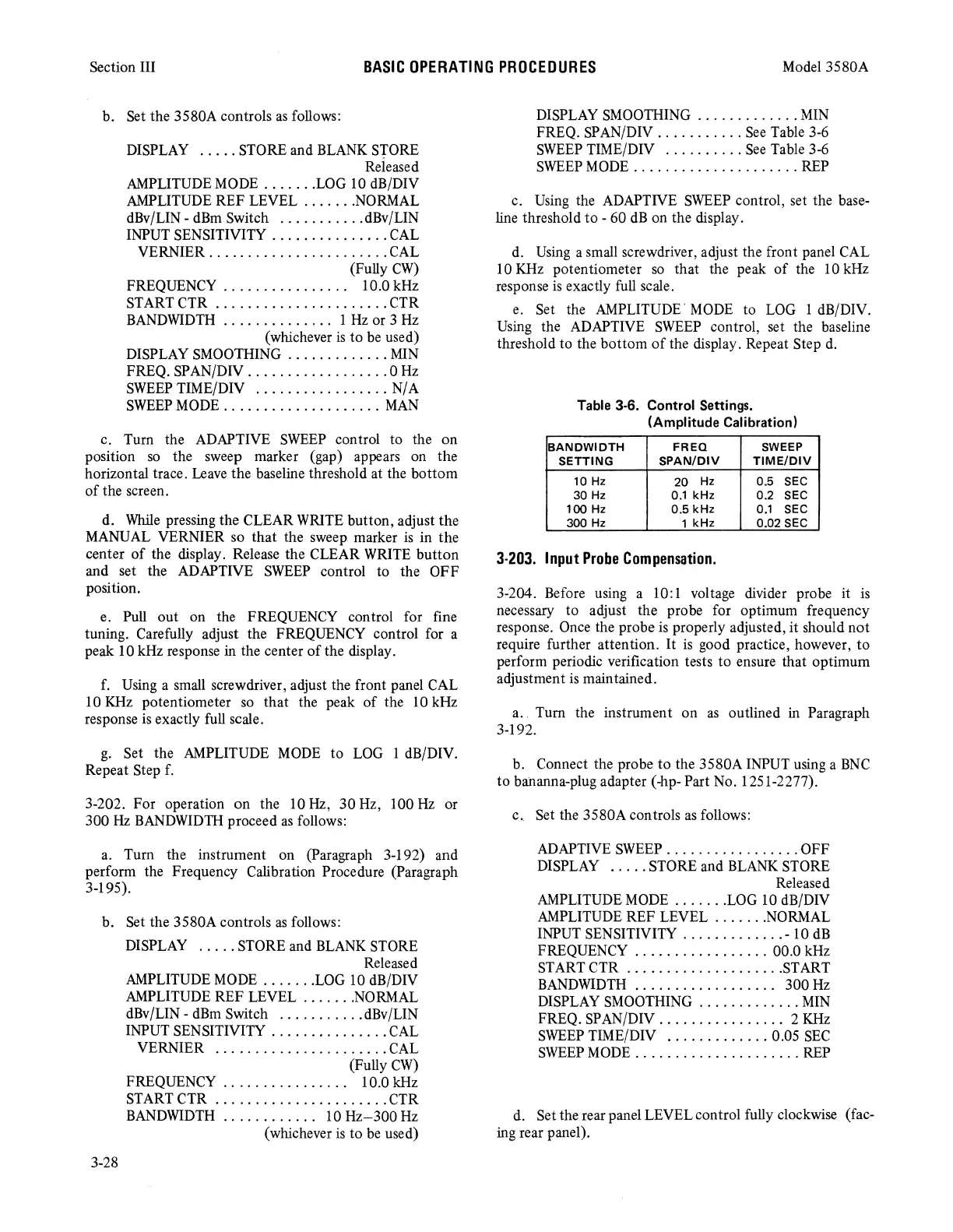
Table 3-6. Control Settings.
(Amplitude Calibration)
BANDWIDTH
FREQ
SWEEP
SETTING
SPAN/DIV
TIME/DIV
10
Hz
20
Hz
0.5
SEC
30
Hz
0.1
kHz 0.2
SEC
100
Hz
0.5 kHz
0.1
SEC
300
Hz
1 kHz 0.02
SEC
3-203.
Input
Probe
Compensation.
3-204. Before using a 10:1 voltage divider probe it
is
necessary
to
adjust the probe for optimum frequency
response. Once the probe
is
properly adjusted,
it
should
not
require further attention.
It
is
good practice, however,
to
perform periodic verification tests
to
ensure that optimum
adjustment
is
maintained.
a .. Turn the instrument
on
as
outlined in Paragraph
3-192.
b. Connect the probe
to
the 3580A INPUT using a
BNC
to
bahanna-plug adapter (-hp- Part No. 1251-2277).
c..
Set the 3580A controls
as
follows:
ADAPTIVE
SWEEP
.................
-OFF
DISPLAY
.....
STORE and BLANK STORE
Released
AMPLITUDE MODE
.......
LOG 10 dB/DIV
AMPLITUDE REF LEVEL
.......
NORMAL
INPUT SENSITIVITY
.............
- 10 dB
FREQUENCY
.................
00.0 kHz
START
CTR
....................
START
BANDWIDTH . . . . . . . . . . . . . . . . . .
300
Hz
DISPLAY SMOOTHING
.............
MIN
FREQ. SPAN/DIV
................
2 KHz
SWEEP
TIME/DIV
.............
0.05
SEC
SWEEP
MODE
.....................
REP
d. Set the rear panel LEVEL control fully clockwise (fac-
ing rear panel).