Section III
GENERAL
OPERATING
INFORMATION
Model 3580A
allow at least
50%
of
the display range to be used.
If
the
Adaptive Sweep
is
not
to be used
in
the Log mode, be sure
the ADAPTIVE SWEEP control
is
in
the OFF position.
3-156. Adaptive Sweep Marker.
When
the ADAPTIVE
SWEEP
control
is
set to the
ON
position, a sweep marker
appears on the display. The sweep marker
is
a blank spot or
gap
in the trace that indicates the position
of
the frequency
sweep. The sweep marker
is
provided because the digital
memory
that
generates the display does not track the
fast-forward and fast-backward excursions
of
the Adaptive .
Sweep. The sweep marker enables the operator to observe
these excursions, making it easy to verify that the Adaptive
Sweep
is
operating properly.
3-157. In some cases it may
be
desirable to display the
sweep marker without using the Adaptive Sweep. This can
be
done in the
linear
and Log 10
dB
modes by setting the
ADAPTIVE
SWEEP
control to the
ON
position and leaving
the baseline threshold at the bottom
of
the display.
With
the baseline threshold at the bottom
of
the display, the
video level exceeds the threshold level causing the instru-
ment
to
continually sweep at the panel-selected rate.
3-158.
Digitally-Stored
Display.
3-159. A unique feature
of
the 3580A
is
its digitally-stored
display. The digitally-stored display provides a number
of
unusual operating conveniences. For example, display
adjustments
are
not required when the sweep parameters
are changed. The digitally-stored trace
is
automatically
cleared and updated at the correct rate. The INTENSITY
and FOCUS controls have the same effect
as
those
of
a
regular oscilloscope.
Once
they are set, they
do
not
need to
be readjusted. Moreover, the INTENSITY control can
be
set to any level without danger of burning the CRT face.
Digital storage provides a bright, crips, flicker-free presenta-
tion. There
is
no blooming
of
display ambiguity.
3-160. One
of
the major advantages
of
digital storage
is
its
ability to retain a trace indefinitely, i.e.,
as
long
as
power
is
applied to the instrument.
When
a
single
sweep
is
made, the
trace that
is
generated
will
continue
to
be displayed until
the CLEAR WRITE button
is
pressed or until it
is
replaced
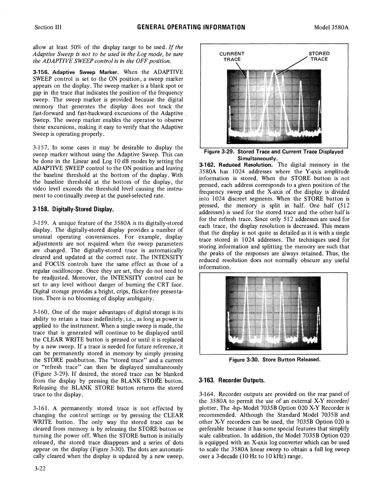
by a new sweep.
If
a trace
is
needed for future reference, it
can be permanently stored in memory by simply pressing
the STORE pushbutton. The "stored trace" and a current
or "refresh trace" can then
be
displayed simultaneously
(Figure 3-29).
If
desired, the stored trace can
be
blanked
from the display by pressing the BLANK STOIIB button.
Releasing the BLANK STORE button returns the stored
trace
to
the display.
3-161. A permanently stored trace
is
not effected by
changing the control settings or by pressing the CLEAR
WRITE button. The only way the stored trace can
be
cleared from memory
is
by releasing the STORE button or
turning the power off.
When
the STORE button
is
initially
released, the stored trace disappears and a series
of
dots
appear on the display (Figure 3-30). The dots are automati-
cally cleared when the display
is
updated by a new sweep.
3-22
STORED
TRACE
Figure 3-29. Stored Trace and Current Trace Displayed
Simultaneously.
3-162. Reduced Resolution. The digital memory in the
3580A has 1024 addresses where the Y-axis amplitude
information
is
stored.
When
the STORE button
is
not
pressed, each address corresponds
to
a
given
position
of
the
frequency sweep and the X-axis
of
the display is divided
into 1024 discreet segments.
When
the STORE button
is
pressed, the memory
is
split in half. One half (512
addresses)
is
used for the stored trace and the other half
is
for the refresh trace. Since only 512 addresses are used for
each trace, the display resolution is decreased. This means
that the display
is
not
quite
as
detailed
as
it
is
with a single
trace stored in 1024 addresses. The techniques used for
storing information and splitting the memory are such that
the peaks
of
the responses are always retained. Thus, the
reduced resolution does not normally obscure any useful
information.
Figure 3-30. Store Button Released.
.3-163.
Recorder
Outputs.
3-164. Recorder outputs are provided on the rear panel
of
the 3580A to permit the use
of
an external
X-Y
recorder/
plotter. The -hp- Model 7035B Option 020
X-Y
Recorder
is
recommended. Although the Standard Model 7035B and
other
X-Y
recorders can
be
used, the 7035B Option 020
is
preferable because it has some special features that simplify
scale calibration. In addition, the Model 7035B Option 020
is
equipped with
an
X-axis
log converter which can be used
to scale the 3580A linear sweep to obtain a full log sweep
over a 3-decade (10
Hz
to 10 kHz) range.