Section V
PERFORMANCE
TESTS
Model 3580A
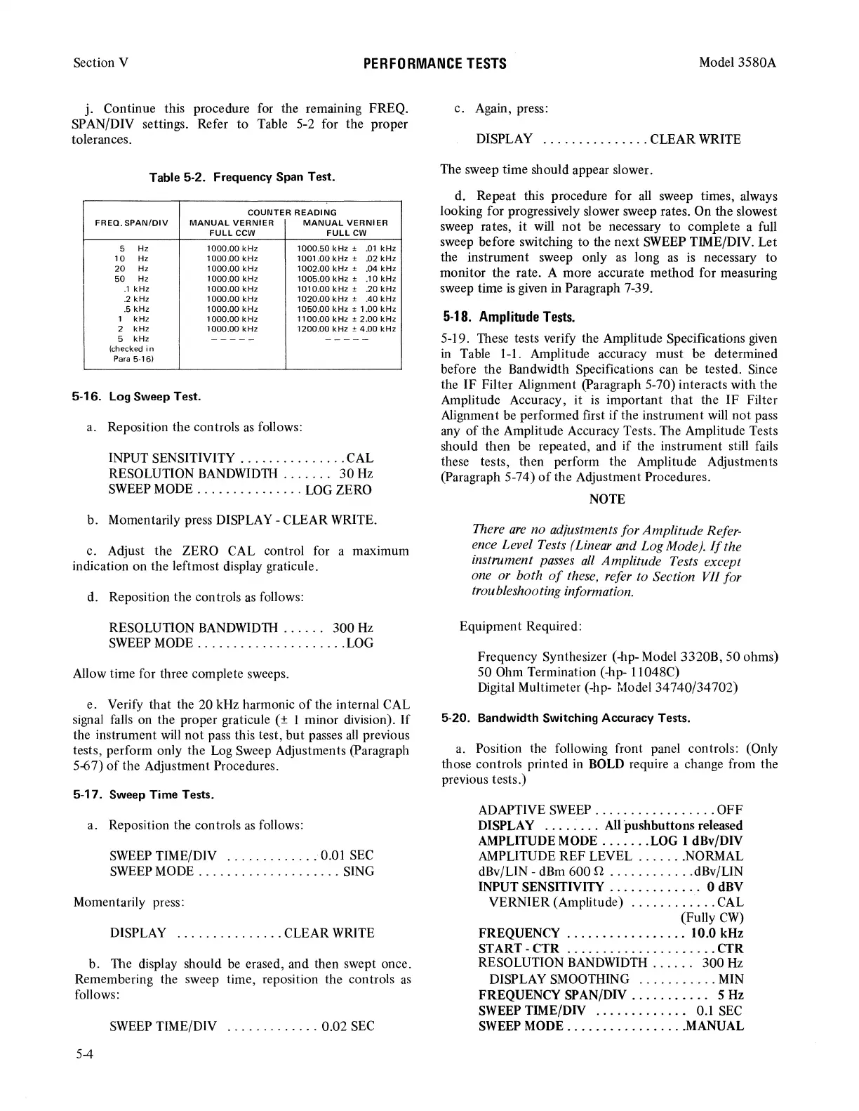
j. Continue this procedure for the remammg FREQ.
SPAN/DIV settings. Refer
to
Table 5-2 for the proper
tolerances.
Table 5-2. Frequency Span Test.
COUNTER
READING
FREQ.
SPAN/DIV
MANUAL
VERNIER
MANUAL
VERNIER
FULLCCW
FULL
CW
5
Hz
1000.00
kHz
1000
.50
kHz
±
.01
kHz
10
Hz
1000.00
kHz
1001.00
kHz
± .02
kHz
20
Hz
1000.00
kHz
1002
.00
kHz
±
.04
kHz
50
Hz
1000.00
kHz
1005.00
kHz
±
.10
kHz
.1
kHz
1000.00
kHz
1010.00
kHz
± .20
kHz
.2
kHz
1000.00
kHz
1020.00
kHz
±
.40
kHz
.5
kHz
1000.00
kHz
1050.00
kHz
±
1.00
kHz
1
kHz
1000.00
kHz
1100.00
kHz±
2.00
kHz
2
kHz
1000.00
kHz
1200.00
kHz
± 4.00
kHz
5
kHz
-----
-----
(checked
in
Para
5-16)
5-16. Log Sweep Test.
a. Reposition the controls
as
follows:
INPUT SENSITIVITY
...............
CAL
RESOLUTION
BANDWIDTH
. . . . . . .
30
Hz
SWEEP
MODE
...............
LOG
ZERO
b. Momentarily press DISPLAY - CLEAR WRITE.
c. Adjust the ZERO CAL control for a maximum
indication on the leftmost display graticule.
d. Reposition the controls
as
follows:
RESOLUTION
BANDWIDTH
. . . . . . 300
Hz
SWEEP
MODE
.....................
LOG
Allow time for three complete sweeps.
e. Verify that the 20 kHz harmonic
of
the internal CAL
signal falls on the proper graticule ( ± 1 minor division).
If
the instrument
will
not
pass this test, but passes
all
previous
tests, perform only the Log Sweep Adjustments (Paragraph
5-67)
of
the Adjustment Procedures.
5-17. Sweep Time Tests.
a. Reposition the controls
as
follows:
SWEEP
TIME/DIV
.............
0.01
SEC
SWEEP
MODE
....................
SING
Momentarily press:
DISPLAY
...............
CLEAR WRITE
b. The display should
be
erased, and then swept once.
Remembering the sweep time, reposition the controls
as
follows:
SWEEP
TIME/DIV
.............
0.02
SEC
5-4
c. Again, press:
DISPLAY
...............
CLEAR WRITE
The sweep time should appear slower.
d. Repeat this procedure for
all
sweep times, always
looking for progressively slower sweep rates. On the slowest
sweep rates,
it
will
not
be necessary
to
complete a full
sweep before switching
to
the next SWEEP TIME/DIV. Let
the instrument sweep only
as
long
as
is
necessary
to
monitor the rate. A more accurate method for measuring
sweep time
is
given in Paragraph 7-39.
5-18.
Amplitude
Tests.
5-19. These tests verify the Amplitude Specifications given
in
Table 1-1. Amplitude accuracy must be determined
before the Bandwidth Specifications can
be
tested. Since
the
IF
Filter Alignment (Paragraph 5-70) interacts with the
Amplitude Accuracy,
it
is important that the
IF
Filter
Alignment be performed first
if
the instrument will
not
pass
any
of
the Amplitude Accuracy Tests. The Amplitude Tests
should then
be
repeated, and
if
the instrument still fails
these tests, then perform the Amplitude Adjustments
(Paragraph 5-74)
of
the Adjustment Procedures.
NOTE
There
are
no adjustments for Amplitude Refer-
ence Level Tests (Linear and Log Mode).
If
the
instrument
passes
all
Amplitude Tests except
one or both
of
these, refer to Section VII for
troubleshooting information.
Equipment Required:
Frequency Synthesizer (-hp- Model 3320B, 50 ohms)
50 Ohm Termination (-hp- 11048C)
Digital Multimeter (-hp- Model 34740/34702)
5-20. Bandwidth Switching Accuracy Tests.
a. Position the following front panel controls: (Only
those controls printed
in
BOLD
require a change from the
previous tests.)
ADAPTIVE
SWEEP
.................
OFF
DISPLAY . . . . . . . .
All
pushbuttons released
AMPLITUDE MODE
......
.
WG
1 dBv/DIV
AMPLITUDE REF LEVEL
.......
NORMAL
dBv/LIN - dBm 600 n
............
dBv/LIN
INPUT SENSITIVITY . . . . . . . . . . . . . 0 dBV
VERNIER (Amplitude)
............
CAL
(Fully
CW)
FREQUENCY
.................
10.0 kHz
ST ART - CTR
.....................
CTR
RESOLUTION BANDWIDTH . . . . . . 300 Hz
DISPLAY SMOOTHING
...........
MIN
FREQUENCY SPAN/DIV
...........
5
Hz
SWEEP
TIME/DIV . . . . . . . . . . . . . 0.1
SEC
SWEEP
MODE
.................
MANUAL