Model 3580A
PERFORMANCE
TESTS
Section V
Option 002: Set dBm 900
n/LIN
- dBm 600 n
switch
to
dBm 900
n;
set INPUT
MODE
switch
to
UNBAL.
b. Connect a properly terminated frequency synthe-
sizer
to
the 3 580A INPUT and adjust the source for a
10 kHz, 0 dBV
output
level
(-
20 dBm 900 n for instru-
ments with Option 002).
NOTE
See Table 5-3 for the proper level to use with
your
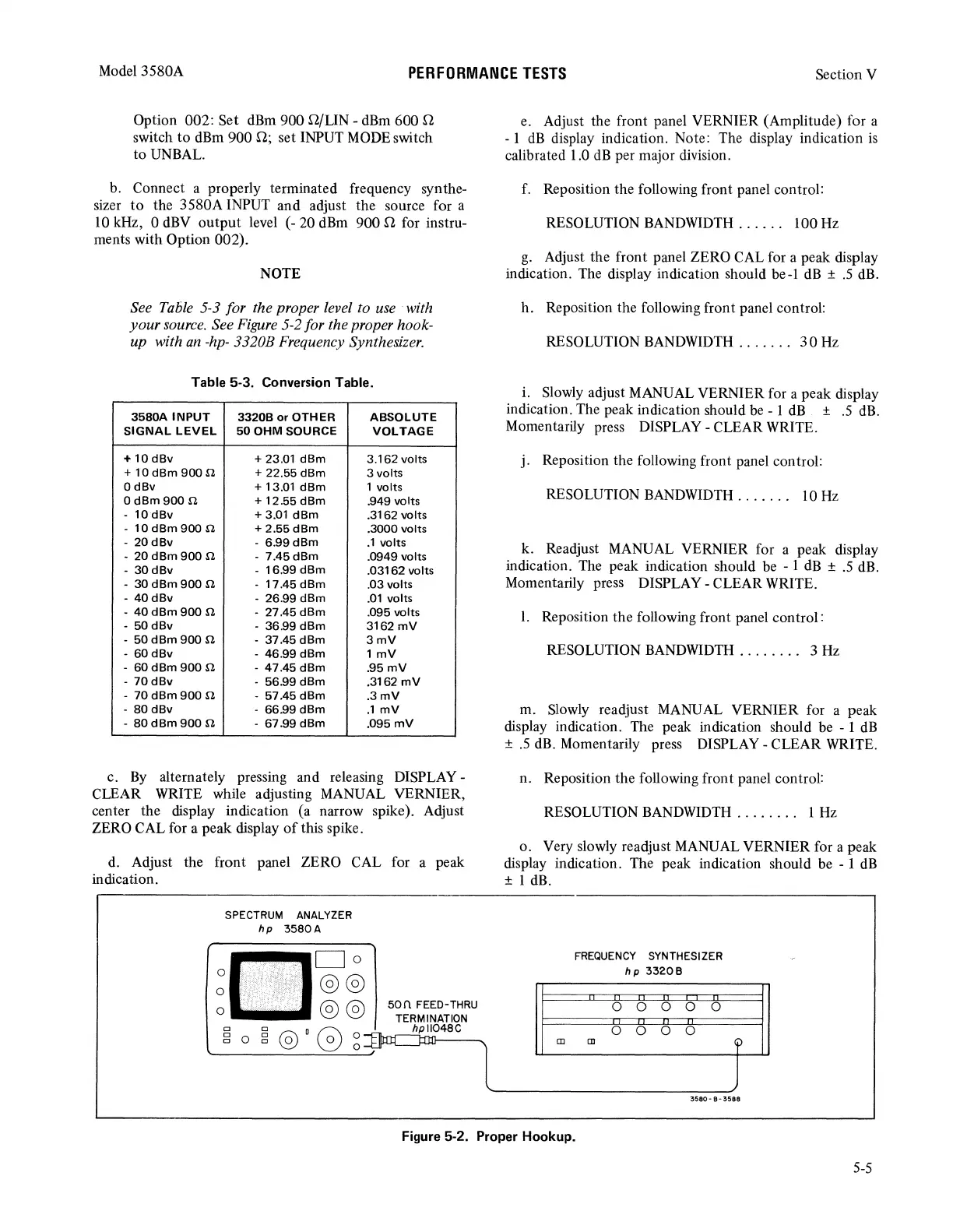
source. See Figure 5-2 for the proper hook-
up with
an
-hp-
3320B Frequency Synthesizer.
Table 5-3. Conversion Table.
3580A
INPUT
33208
or
OTHER
ABSOLUTE
SIGNAL
LEVEL
50
OHM
SOURCE
VOLTAGE
+
10
dBv
+ 23.01
dBm
3.162volts
+
10dBm
9000
+ 22.55 dBm 3 volts
OdBv
+ 13.01
dBm
1 volts
OdBm900
n
+ 12.55
dBm
.949 volts
- 10
dBv
+ 3.01
dBm
.3162 volts
- 10
dBm
900
.n
+
2.55dBm
.3000 volts
- 20
dBv
-
6.99dBm
.1
volts
- 20
dBm
900
.n
-
7.45dBm
.0949 volts
- 30
dBv
- 16.99
dBm
.03162 volts
- 30
dBm
900
.n
-17.45dBm
.
03
volts
-
40dBv
- 26.99
dBm
.01
volts
-
40
dBm
900
.n
-
27.45dBm
.095 volts
- 50
dBv
- 36.99
dBm
3162
mV
- 50
dBm
900
.n
- 37.45
dBm
3mV
- 60
dBv
-
46.99
dBm
1
mV
- 60
dBm
900
.n
- 47.45
dBm
.95mV
-
70
dBv
- 56.99
dBm
.3162
mV
-
70dBm900
n
- 57.45
dBm
.3mV
- 80
dBv
- 66.99
dBm
.1
mV
-
80
dBm
900
.n
- 67.99
dBm
.095
mV
c.
By
alternately pressing and releasing DISPLAY -
CLEAR WRITE while adjusting MANUAL VERNIER,
center the display indication (a narrow spike). Adjust
ZERO CAL for a peak display
of
this spike.
d.
Adjust the front panel ZERO CAL for a peak
indication.
0
0
0
SPECTRUM
ANALYZER
hp
3580A
Do
@@
@@
50n
FEED-THRU
TERMINATION
...r.c
hpll048C
:1u:
;;-"
e. Adjust the front panel VERNIER (Amplitude) for a
- 1
dB
display indication. Note: The display indication
is
calibrated 1.0
dB
per major division.
f.
Reposition the following front panel control:
RESOLUTION BANDWIDTH . . . . . . 100 Hz
g.
Adjust the front panel ZERO CAL for a peak display
indication. The display indication should be-1
dB
±
.5
dB.
h. Reposition the following front panel control:
RESOLUTION BANDWIDTH
.......
30
Hz
i.
Slowly adjust MANUAL VERNIER for a peak display
indication. The peak indication should be - 1
dB
±
.5
dB.
Momentarily press DISPLAY - CLEAR WRITE.
j. Reposition the following front panel control:
RESOLUTION BANDWIDTH . . . . . . . 10
Hz
k. Readjust MANUAL VERNIER for a peak display
indication. The peak indication should be - 1
dB
±
.5
dB.
Momentarily press DISPLAY - CLEAR WRITE .
I. Reposition the following front panel control:
RESOLUTION BANDWIDTH . . . . . . . . 3 Hz
m. Slowly readjust MANUAL VERNIER for a peak
display indication. The peak indication should be - 1
dB
±
.5
dB.
Momentarily press DISPLAY - CLEAR WRITE.
n. Reposition the following front panel control:
RESOLUTION BANDWIDTH . . . . . . . . 1 Hz
o. Very slowly readjust MANUAL VERNIER for a peak
display indication. The peak indication should be - 1
dB
± 1 dB.
Ill
FREQUENCY
SYNTHESIZER
hp
33208
0
0
0 0 0
0
0
0 0
[]]
'i>
3580-
B-
3588
Figure 5-2. Proper Hookup.
5-5