Model 3580A
GENERAL
OPERATING
INFORMATION
Section III
The instrument should
not
be
left
in
the
CHARGE mode for prolonged periods. A
charge
period
of
14 hours
is
sufficient to
recharge
a fully discharged battery pack. Ex-
tended periods
of
overcharge
in
ambient tem-
peratures exceeding 30° C ( 86° F) will severely
degrade battery life and capacity by causing the
cells to overheat.
3-186. Temperature Limits. To prevent battery damage,
the following temperature limits must
be
observed:
a.
Operating Temperature: 0° C ( + 3
2°
F) to + 40° C
(+
104°F)
b. Charge Temperature Range: 0°C
(+
32°F)
to+
40°C
(+ 104° F)
c. Storage Temperature Range: - 40° C
(-
40°
F)
to
+ 50°C
(+
122°F)
3-187.
Option
002.
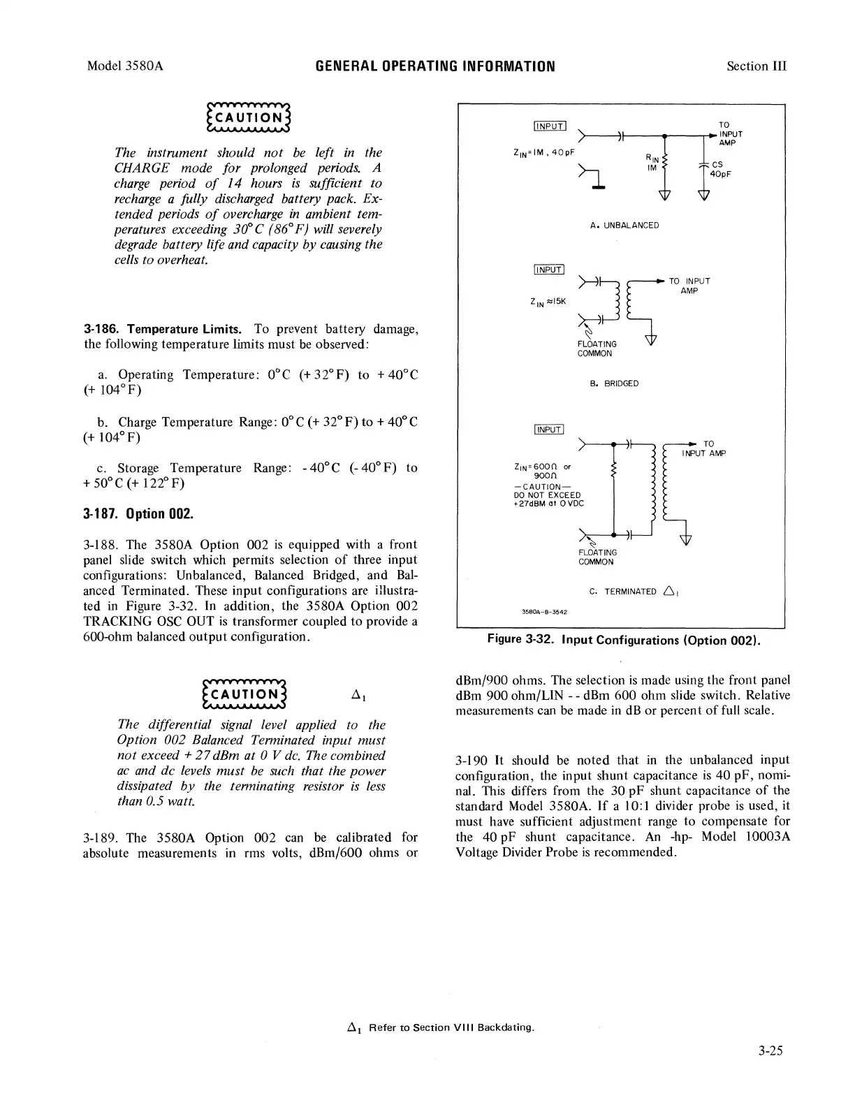
3-188. The 3580A Option 002
is
equipped with a front
panel slide switch which permits selection
of
three input
configurations: Unbalanced, Balanced Bridged, and
Bal-
anced Terminated. These input configurations are illustra-
ted
in
Figure 3-32. In addition, the 3580A Option 002
TRACKING
OSC
OUT
is
transformer coupled
to
provide a
600-ohm balanced
output
configuration.
~I
The differential
signal
level applied to the
Option 002 Balanced Terminated input must
not
exceed+
27
dBm at 0 V
de.
The combined
ac
and de levels
must
be
such
that the power
dissipated
by
the terminating resistor
is
less
than 0.5 watt.
3-189. The 3580A Option 002 can
be
calibrated for
absolute measurements
in
rms volts, dBm/600 ohms or
ffiIBill
)----71li~PUT
AMP
z
1
N~IM,40pF
)..-,
~~N
Tes
.
.J..
w
40pF
A.
UNBALANCED
~J
~TO
INPUT
AMP
~
FLOATING
COMMON
Z1N °
6000.
or
90011
-CAUTION-
DO
NOT
EXCEED
+ 27dBM
at
0
VDC
B.
BRIDGED
~
FLOATING
COMMON
C.
TERMINATED
61
3580A~B-3542
TO
INPUT
AMP
Figure
3-32. Input Configurations (Option
002).
dBm/900 ohms. The selection
is
made using the front panel
dBm
900 ohm/LIN - - dBm 600 ohm slide switch. Relative
measurements can be made
in
dB
or percent
of
full scale.
3-190
It
should be noted that
in
the unbalanced input
configuration, the input shunt capacitance
is
40 pF, nomi-
nal. This differs from the 30
pF
shunt capacitance
of
the
standard Model 3580A.
If
a 10:1 divider probe
is
used, it
must
have
sufficient adjustment range to compensate for
the 40 pF shunt capacitance.
An
-hp- Model 10003A
Voltage Divider Probe
is
recommended.
~
1
Refer
to
Section
VIII
Backdating.
3-25