Model 3580A Section II
SECTION
II
INSTALLATION
2-1.
INTRODUCTION.
2-2. This section contains information and instructions
necessary for installing and shipping the Model 3580A
Spectrum Analyzer. Included are initial inspection proce-
dures, power and grounding requirements, environmental
information, installation instructions and instructions for
repackaging for shipment.
2-3.
INITIAL
INSPECTION.
2-4. This instrument
was
carefully inspected
both
mechan-
ically and electrically before shipment.
It
should be free
of
mars or scratches and in perfect electrical order upon
receipt. To confirm this, the instrument should be in-
spected for physical damage incurred in transit.
If
the
instrument
was
damaged in transit, file a claim with the
carrier. Check for supplied accessories (Paragraph 1-11) and
test the electrical performance
of
the instrument using the
performance test procedures outlined in Section
V.
If
there
is
damage
or
deficiency,
see
the warranty in the front
of
this manual.
2-5.
POWER
REQUIREMENTS.
2-6. The Model 3580A can be operated from any power
source supplying 100 V, 120
V,
220 V or 240 V (+
5%
- 10%), 48 Hz to
440
Hz. Power dissipation
is
35 watts,
maximum. Refer
to
Paragraph 3-192 (Section
III)
for the
Instrument
Tum
On procedure.
2-7.
Power
Cords
And
Receptacles.
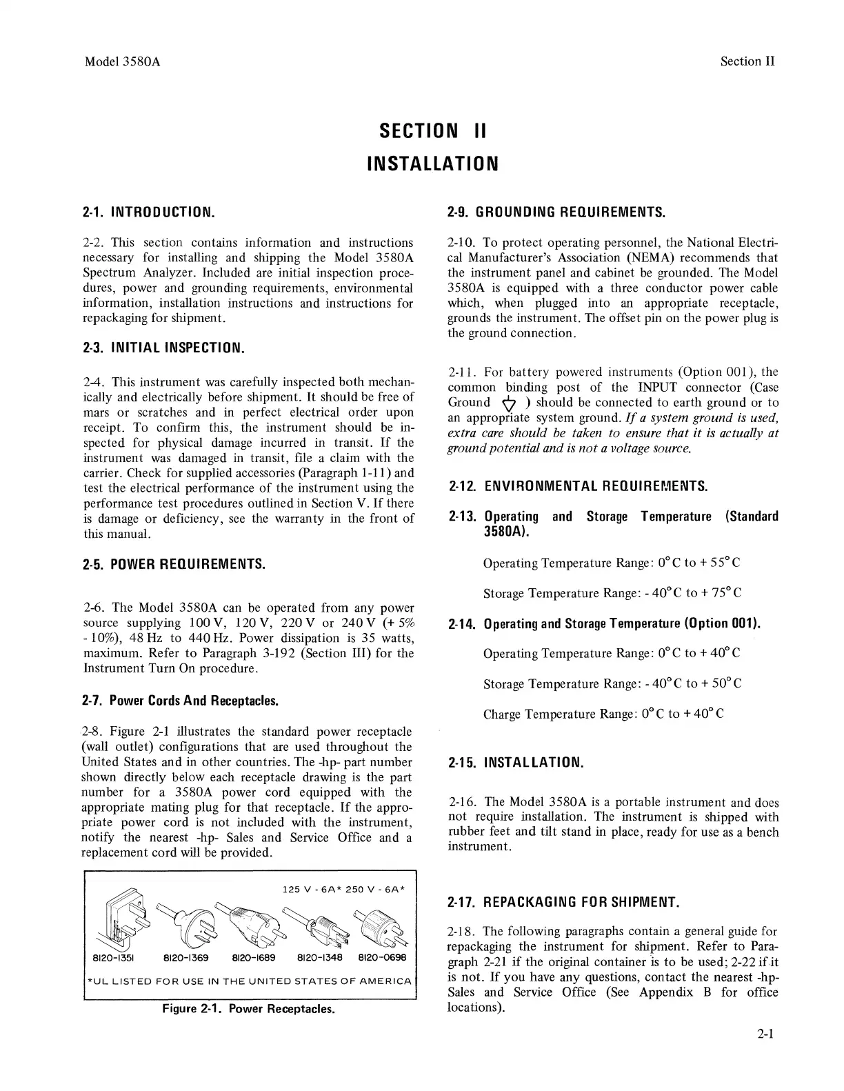
2-8. Figure
2-1
illustrates the standard power receptacle
(wall outlet) configurations that are used throughout the
United States and in other countries. The -hp- part number
shown directly below each receptacle drawing
is
the part
number for a 3580A power cord equipped with the
appropriate mating plug for that receptacle.
If
the appro-
priate power cord
is
not
included with the instrument,
notify the nearest -hp- Sales and Service Office and a
replacement cord will be provided.
*UL
LISTED
FOR
USE
IN
THE
UNITED
STATES
OF
AMERICA
Figure 2-1. Power Receptacles.
2-9.
GROUNDING
REQUIREMENTS.
2-10. To protect operating personnel, the National Electri-
cal Manufacturer's Association (NEMA) recommends that
the instrument panel and cabinet be grounded. The Model
3580A
is
equipped with a three conductor power cable
which, when plugged into an appropriate receptacle,
grounds the instrument. The offset pin on the power plug
is
the ground connection.
2-11. For battery powered instruments (Option 001), the
common binding post
of
the INPUT connector (Case
Ground ¢ ) should be connected
to
earth ground or
to
an appropriate system ground.
If
a system ground
is
used,
extra
care
should
be
taken to ensure that
it
is
actually at
ground potential and
is
not
a voltage source.
2-12.
ENVIRONMENTAL
REQUIREMENTS.
2-13.
Operating
and
Storage
Temperature
(Standard
3580A).
Operating Temperature Range: 0°C
to+
55°C
Storage Temperature Range: - 40°C
to+
75° C
2-14.
Operating
and
Storage
Temperature
(Option
001).
Operating Temperature Range: 0° C
to
+ 40° C
Storage Temperature Range: - 40°C
to+
50°C
Charge Temperature Range: 0°C
to
+40°C
2-15.
INSTALLATION.
2-16. The Model 3580A
is
a portable instrument and does
not require installation. The instrument
is
shipped with
rubber feet and tilt stand in place, ready for use
as
a bench
instrument.
2-17.
REPACKAGING
FOR
SHIPMENT.
2-18. The following paragraphs contain a general guide for
repackaging the instrument for shipment. Refer
to
Para-
graph
2-21
if
the original container
l.s
to
be used; 2-22
ifit
is
not.
If
you
have any questions, contact the nearest -hp-
Sales and Service Office (See Appendix B for office
locations).
2-1